When measuring things, pink noise isn’t the only option.
Please Remember:
The opinions expressed are mine only. These opinions do not necessarily reflect anybody else’s opinions. I do not own, operate, manage, or represent any band, venue, or company that I talk about, unless explicitly noted.

 use this image for something else? Great! Click it for the link to a high-res or resolution-independent version.
Back in school, we learned how to measure the frequency response of live-audio rigs using a dual FFT system. I didn’t realize at the time how important the idea of measuring would become to me. As a disliker of audio mythology, I find myself having less and less patience for statements like “I swear, it sounds better when we change to this super-spendy cable over here.”
Does it? Are you sure? Did you measure anything? If you can hear it, you should be able to measure it. Make any statement you want, but at least try to back it up with real data.
Anyway.
I’m by no means an expert on all aspects of measuring sound equipment. At the same time, I’ve gotten to the point where I think I can pass on some observations. The point of this article is to have a bit of a chat regarding some signals that can be used to measure audio gear.
Tones and Noise
When trying to measure sound equipment, we almost always need some kind of “stimulus” signal. The stimulus chosen depends on what we’re trying to figure out. If we want to get our bearings regarding a device’s distortion characteristics, a pure tone (or succession of pure tones) is handy. If we want to know about our gear’s total frequency response, we either need a signal that’s “broadband” at any given point in time, or a succession of signals that can be integrated into a broadband measurement over several points in time.
(Pink noise is an example of a signal that’s broadband at any given time point, whereas a tone sweep has to be integrated over time.)
In any case, the critical characteristic that these stimuli share is this:
A generally-useful measurement stimulus is a signal whose key aspects are well defined and known in advance of the test.
With pure tones, for instance, we know the frequency and voltage-level of the tone being generated. With pink noise, we know that all audio frequencies are present and that the overall signal has equal power per octave. (The level of any particular frequency at any particular point in time is not known in advance, unless a specific sample of noise is used repeatedly.)
Pretty In Pink
Pink noise is a very handy stimulus, especially with the prevalence of measurement systems that show us the transfer function of a device undergoing testing.
When folks are talking about “Dual FFT” measurement, this is what they’re referring to. The idea is to compare a known signal arriving at a device’s input with an unknown signal at the device’s output. In a certain sense, the unknown signal is only “quasi” unknown, because the assumption in play is that the observed output IS the input…plus whatever the measured device did to it.
Pink noise is good for this kind of testing because it can easily be continuous – which allows for testing across an indefinite time span – and also because it is known in advance to contain audio across the entire audible spectrum at all times. (As an added bonus, pink noise is much less annoying to listen to than white noise.) It’s true that with a system that computes transfer functions, you can certainly use something like music playback for a stimulus. Heck, you can even use a live show as the test signal. The system’s measurements are concerned with how the output relates to the input, not the input by itself. The bugaboo, though, is that a stimulus with content covering only part of the audible spectrum can’t give you information about what the system is doing beyond that input signal’s bandwidth. Because pink noise covers the entire audible spectrum (and more) all the time, using it as a stimulus means that you can reliably examine the performance of the system-under-test across the entire measurable range.
Now, this is not to say that pink noise is entirely predictable. Because it is a random or pseudo-random signal, a specific frequency’s level at a specific point in time is unknown until the noise is generated. For example, here’s a spectrogram of pink noise that has been aggressively bandpassed at 1kHz:
The tone at 1kHz never completely disappears, but it’s clearly not at the same level all the time.
A major consequence of this variability is that getting a really usable measurement functionally REQUIRES two measurement points. Since the signal is not entirely known in advance, the reference signal MUST be captured during the measurement process. Although some test rigs can smooth un-referenced pink noise, and display the spectrum as being nominally “flat” (as opposed to sloping downwards from low to high frequencies), the resulting measurements just aren’t as good as they could be. It’s just harder than necessary to do something meaningful with something like this:
Further, any delay caused by the system being measured must be compensated for. If the delay is un-compensated, the measurement validity drops. Even if the frequency response of the measured system is laser-flat, and even if the system has perfect phase response across all relevant frequencies, un-compensated delay will cause this to NOT be reflected in the data. If the dual FFT rig compares an output signal at time “t+delay” to an input signal at “t,” the noise variability means that you’re not actually examining comparable events. (The input signal has moved on from where the output signal is.)
Here’s a simulation of what would happen if you measured a system with 50ms of delay between the input and output…and neglected to compensate for that delay. This kind of delay can easily happen if you’re examining a system via a measurement mic at the FOH mix position, for example.
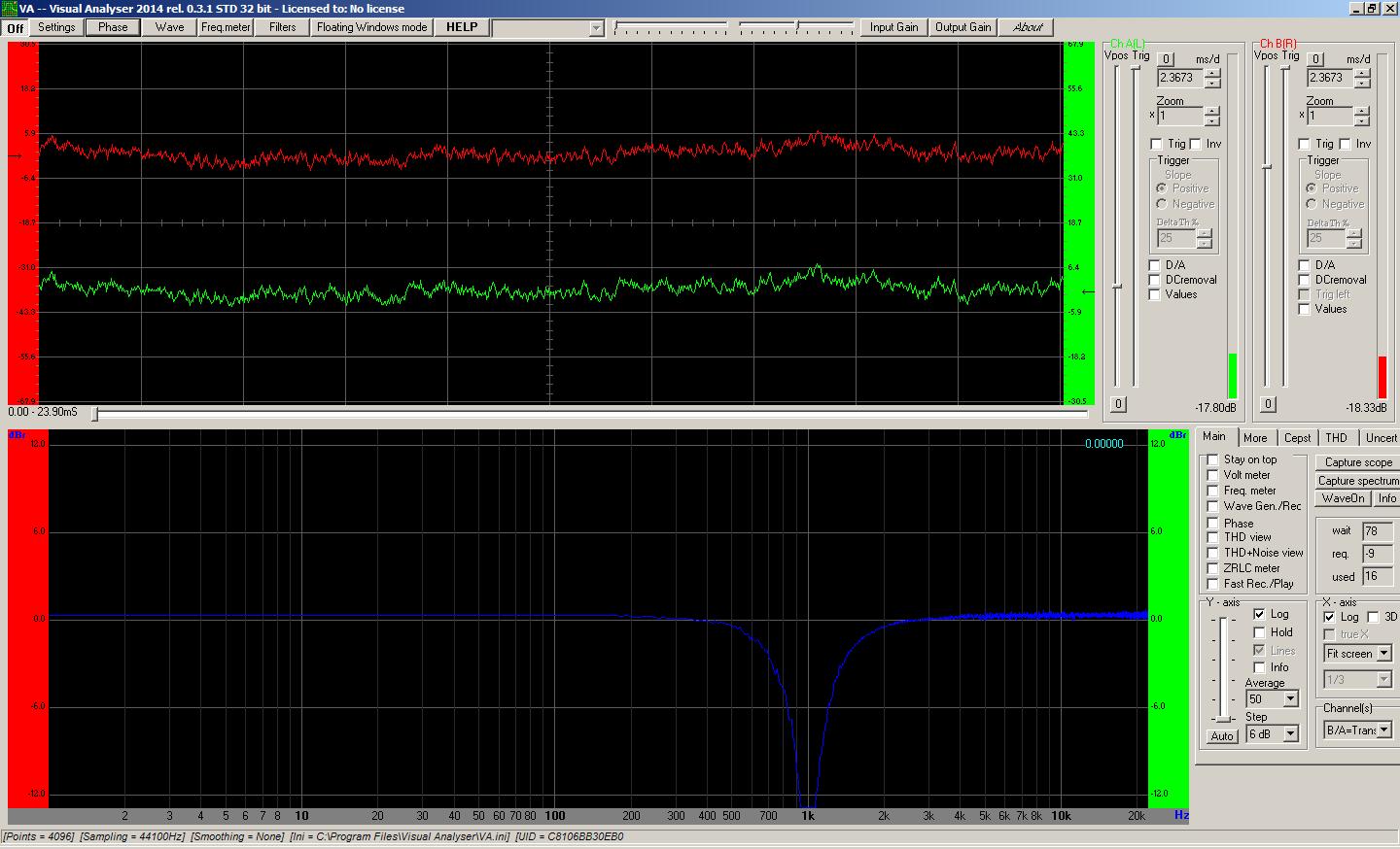
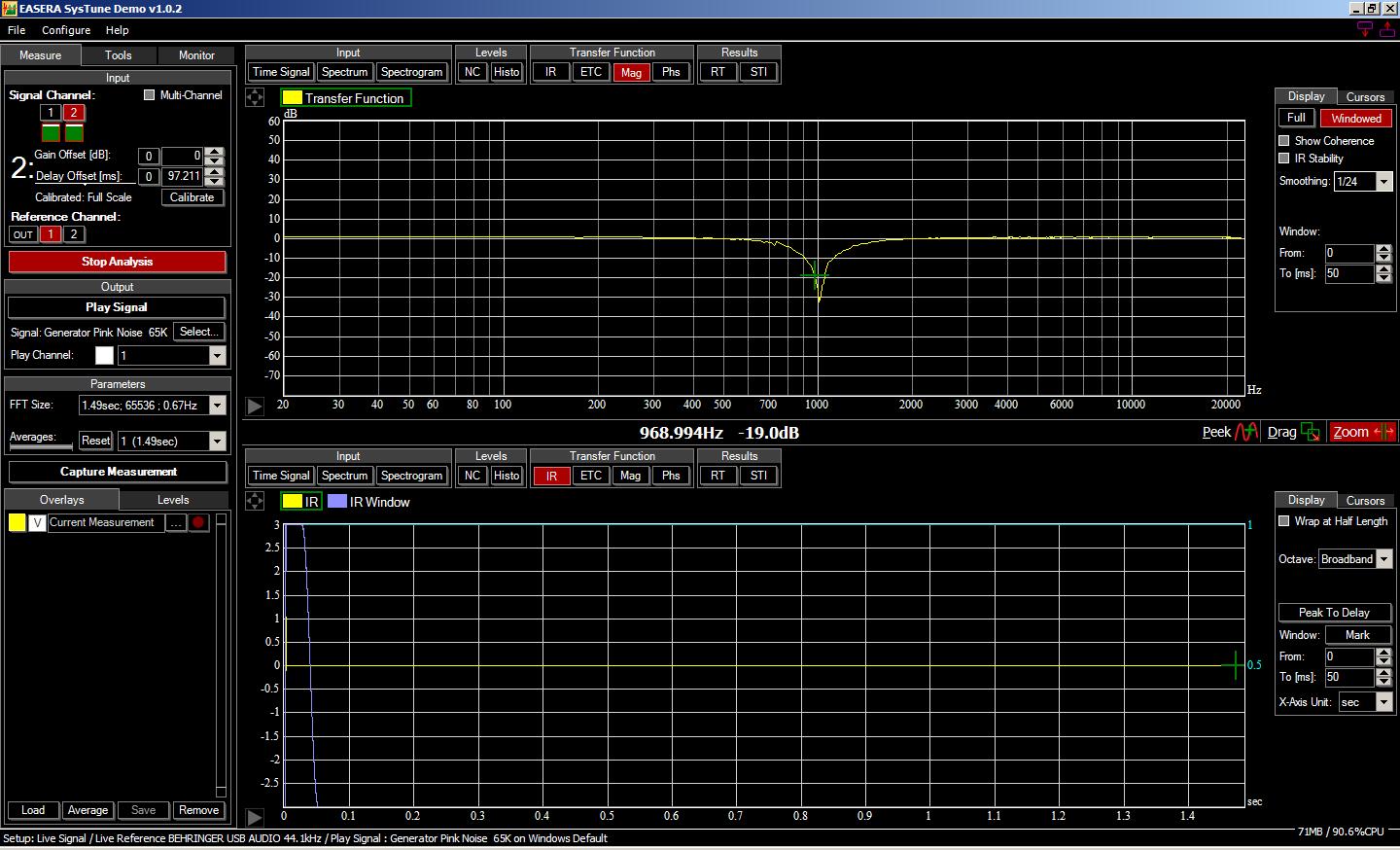
On the flipside, get everything in order and pink noise reliably gets usable measurements across a variety of test rigs, like these views of a notch filter at 1 kHz.
Hey, I Know That Guy…Er, Noise
I’ve known about pink noise for a long while now. What I didn’t know about until recently was a broadband stimulus that Reaper calls “FFT Noise.”
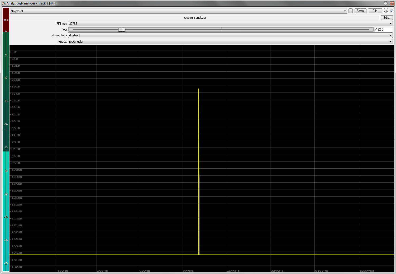
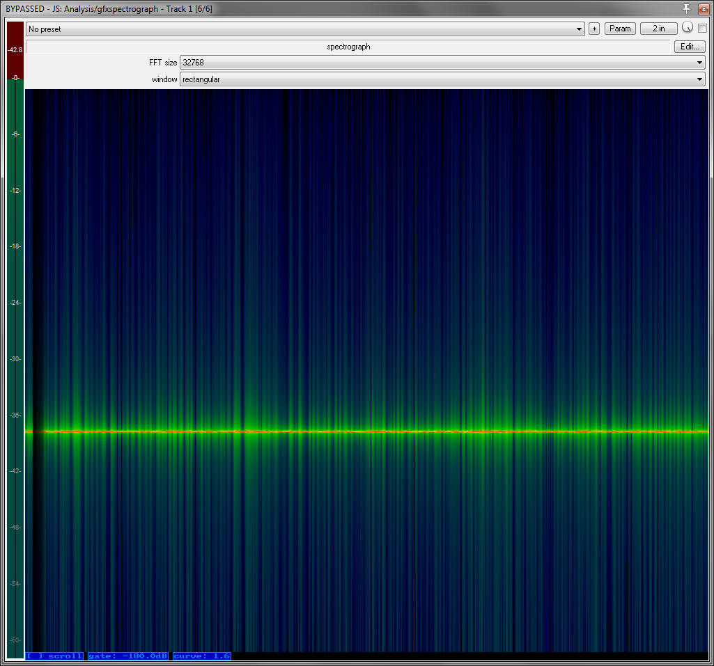
FFT noise is very interesting to me because it is unlike pink noise in key ways. It is dis-contiguous, in that it consists of a repeating “pulse” or “click.” It is also entirely predictable. As far as I can tell, each pulse contains most of the audible spectrum (31 Hz and above) at an unchanging level. For example, here’s a spectrogram of FFT noise with a narrow bandpass filter applied at 1 kHz:

What’s even more interesting is what happens when the test stimulus is configured to “play nicely” with an FFT-based analyzer. You got a preview of that in the preview above. When the analyzer’s FFT size and windowing are set correctly, a trace that handily beats out some dual FFT measurements (in terms of stability and readability) results:
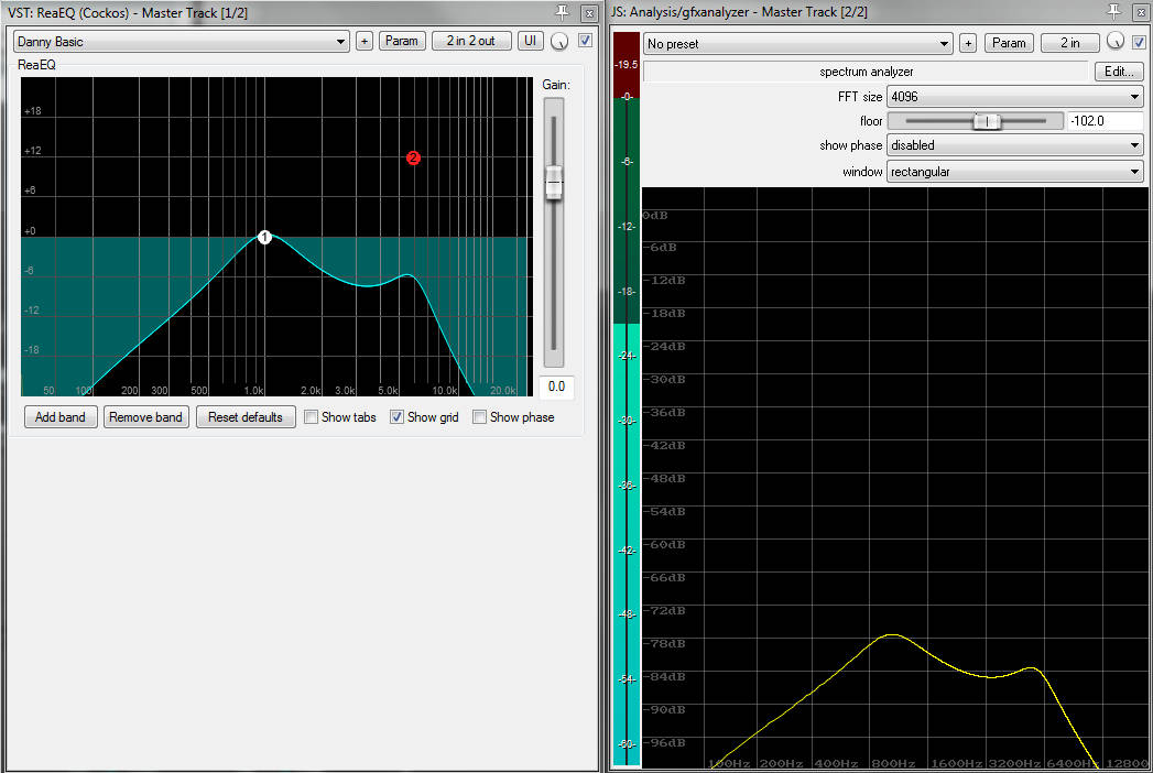
Side note: Yup – the calculated transfer function in ReaEQ seems to be accurate.
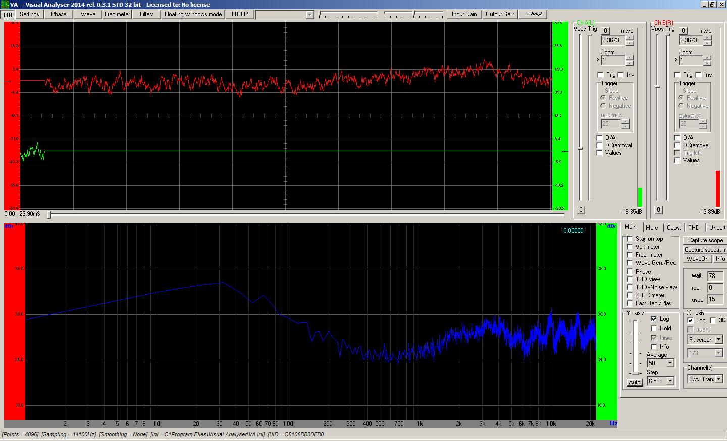
The point here is that, if the test stimulus is precisely known in advance, then you can theoretically get a transfer function without having to record the input-side in real time. If everything is set up correctly, the “known” signal is effectively predetermined in near totality. The need to sample it to “know it” is removed. Unlike pink noise, this stimulus is exactly the same every time. What’s also very intriguing is that this removes the delay of the device-under-test as a major factor. The arrival time of the test signal is almost a non-issue. Although it does appear advantageous to have an analyzer which uses all the same internal timing references as the noise generator (the trace will be rock steady under those conditions), a compatible analysis tool receiving the signal after an unknown delay still delivers a highly readable result:
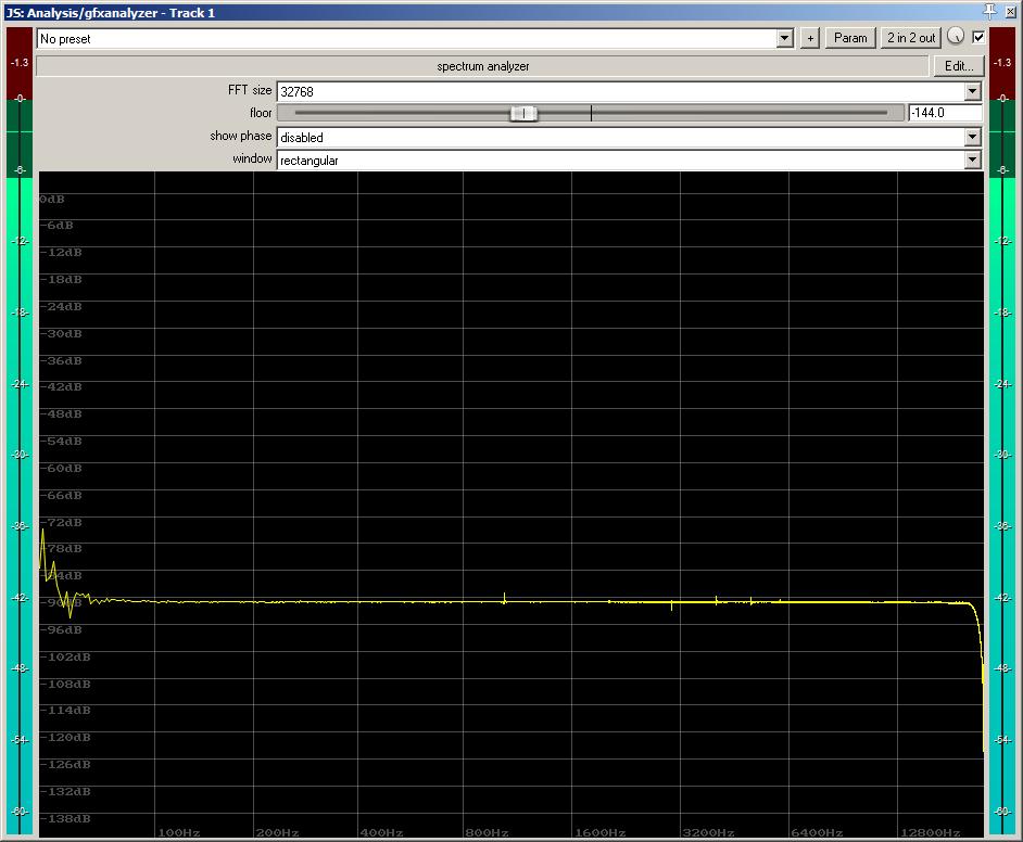
Yes, the cumulative effect of the output from my main computer’s audio interface and the input of my laptop interface is noise, along with some tones that I suppose are some kind of EM interference. You can also see the effect of what I assume is the anti-aliasing filter way over on the right side. (This trace is what gave me the sneaky suspicion that an insufficient amount of test signal exists somewhere below 100 Hz – either that, or the system noise in the bottom octaves is very high.)
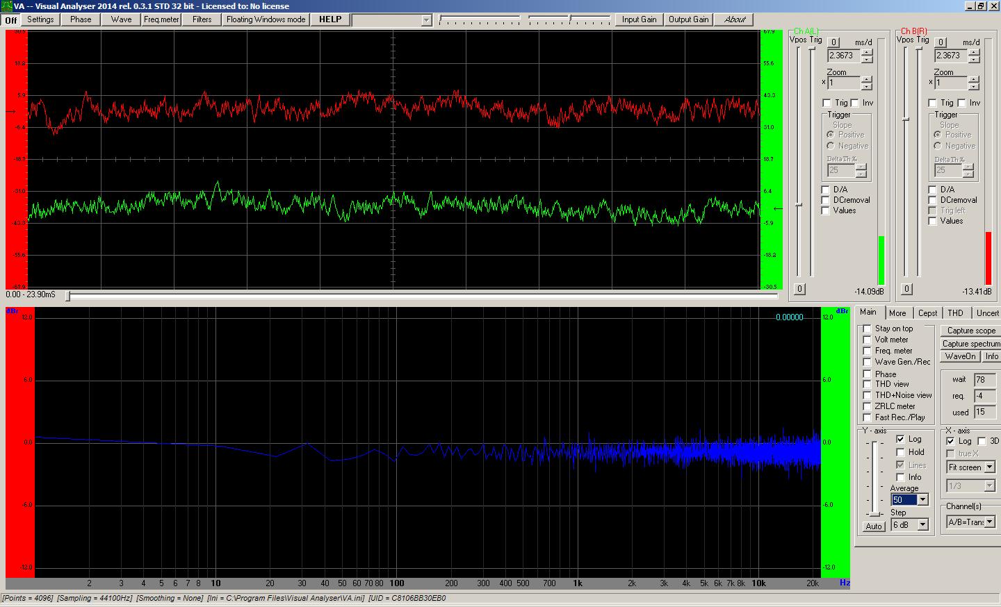
On the surface, this seems rather brilliant, even in the face of its limitations. Instead of having to rig up two measurement points and do delay compensation, you can just do a “one step” measurement. However, getting the stimulus and “any old” analysis tool to be happy with each other is not necessarily automatic. “FFT Noise” in Reaper seems to be very much suited to Reaper’s analysis tools, but it takes a little doing to get, say, Visual Analyzer set up well. When a good configuration IS arrived at, however, Visual Analyzer delivers a very steady trace that basically confirms what I saw in Reaper.
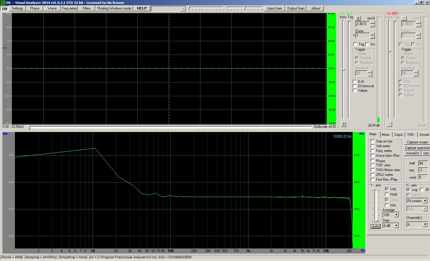
It’s also possible to get a basically usable trace in SysTune, although the demo’s inability to set a long enough average size makes the trace jumpy. Also, Reaper’s FFT noise plugin doesn’t allow for an FFT size that matches the SysTune demo’s FFT size, so some aggressive smoothing is required.
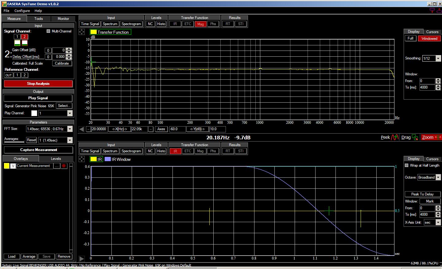
(As a side note, I did find a way to hack Reaper’s FFT noise plugin to get an FFT size of 65536. This fixed the need for smoothing in the frequency domain, but I wasn’t really sure that the net effect of “one big trace bounce every second” was any better than having lots of smaller bounces.)
There’s another issue to discuss as well. With this kind of “single ended” test, noise that would be ignored by a dual FFT rig is a real issue. In a way that’s similar to a differential amplifier in a mic pre, anything that’s common to both measurement points is “rejected” by a system that calculates transfer functions from those points. If the same stimulus+noise signal is present on both channels, then the transfer function is flat. A single-ended measurement can’t deliver the same result, except by completely drowning the noise in the stimulus signal. Whether this is always practical or not is another matter – it wasn’t practical for me while I was getting these screenshots.
The rabbit-hole goes awfully deep, doesn’t it?