Tag Archives: Signal Flow

Case Study: FX When FOH Is Also Monitor World

Two reverbs can help you square certain circles.

Please Remember:

The opinions expressed are mine only. These opinions do not necessarily reflect anybody else’s opinions. I do not own, operate, manage, or represent any band, venue, or company that I talk about, unless explicitly noted.

Want to use this image for something else? Great! Click it for the link to a high-res or resolution-independent version.

The Video

The Script

Let’s say that a band has a new mixing console – one of those “digital rigs in a box” that have come on the scene. The musicians call you in because they need some help getting their monitors dialed up. At some point, the players ask for effects in the monitors: The vocals are too dry, and some reverb would be nice.

So, you crank up an FX send with a reverb inserted on the appropriate bus – and nothing happens.

You then remember that this is meant to be a basic setup, with one console handling both FOH and monitors. Your inputs from the band use pre-fader sends for monitor world, but post-fader sends for FX. Since you weren’t building a mix for FOH, all your faders were all the way down. You don’t know where they would be for a real FOH mix, anyway. If the faders are down, a post-fader send can’t get any signal to an FX bus.

Now, you typically don’t want the monitors to track every level tweak made for FOH, but you DO want the FX sends to be dependent on fader position – otherwise, the “wet-to-dry” ratio would change with every fader adjustment.

So, what do you do?

You can square the circle if you can change the pre/ post send configuration to the FX buses, AND if you can also have two reverbs.

Reverb One becomes the monitor reverb. The sends to that reverb are configured to be pre-fader, so that you don’t have to guess at a fader level. The sends from the reverb return channel should also be pre-fader, so that the monitor reverb doesn’t end up in the main mix.

Reverb Two is then setup to be the FOH reverb. The sends to this reverb from the channels are configured as post-fader. Reverb Two, unlike Reberb One, should have output that’s dependent on the channel fader position. Reverb Two is, of course, kept out of the monitor mixes.

With a setup like this, you don’t need to know the FOH mix in advance in order to dial up FX in the monitors. There is the small downside of having to chew up two FX processors, but that’s not a huge problem if it means getting the players what they need for the best performance.


Case Study: Creating A Virtual Guitar Rig In An Emergency

Distortion + filtering = something that can pass as a guitar amplifier in an emergency.

Please Remember:

The opinions expressed are mine only. These opinions do not necessarily reflect anybody else’s opinions. I do not own, operate, manage, or represent any band, venue, or company that I talk about, unless explicitly noted.

Want to use this image for something else? Great! Click it for the link to a high-res or resolution-independent version.

The Video

The Script

Imagine the scene: You’re setting up a band that has exactly one player with an electric guitar. They get to the gig, and suddenly discover a problem: The power supply for their setup has been left at home. Nobody has a spare, because it’s a specialized power supply – and nobody else plays an electric guitar anyway. The musician in question has no way to get a guitar sound without their rig.

At all.

As in, what they have that you can work with is a guitar and a cable. That’s it.

So, what do you do?

Well, in the worst-case scenario, you just find a direct box, run the guitar completely dry, and limp through it all as best you can.

But that’s not your only option. If you’re willing to get a little creative, you can do better than just having everybody grit their teeth and suffer. To get creative, you need to be able to take their guitar rig apart and put it back together again.

Metaphorically, I mean. You can put the screwdriver away.

What I’m getting at is this question: If you break the guitar rig into signal-processing blocks, what does each block do?

When it comes right down to it, a super-simple guitar amp amounts to three things: Some amount of distortion (including no distortion at all), tone controls, and an output filter stack.
The first two parts might make sense, but what’s that third bit?

The output filtering is either an actual loudspeaker, or something that simulates a loudspeaker for a direct feed. If you remove a speaker’s conversion of electricity to sound pressure waves, what’s left over is essentially a non-adjustable equalizer. Take a look at this frequency-response plot for a 12″ guitar speaker by Eminence: It’s basically a 100 Hz to 5 kHz bandpass filter with some extra bumps and dips.

It’s a fair point to note that different guitar amps and amp sims may have these different blocks happening in different orders. Some might forget about the tone-control block entirely. Some might have additional processing available.

Now then.

The first thing to do is to find an active DI, if you can. Active DI boxes have very high input impedances, which (in short) means that just about any guitar pickup will drive that input without a problem.

Next, if you’re as lucky as I am, you have at your disposal a digital console with a guitar-amp simulation effect. The simulator puts all the processing I talked about into a handy package that gets inserted into a channel.

What if you’re not so lucky, though?

The first component is distortion. If you can’t get distortion that’s basically agreeable, you should skip it entirely. If you must generate your own clipping, your best bet is to find some analog device that you can drive hard. Overloading a digital device almost always sounds terrible, unless that digital device is meant to simulate some other type of circuit.
For instance, if you can dig up an analog mini-mixer, you can drive the snot out of both the input and output sides to get a good bit of crunch. (You can also use far less gain on either or both ends, if you prefer.)

Of course, the result of that sounds pretty terrible. The distortion products are unfiltered, so there’s a huge amount of information up in the high reaches of the audible spectrum. To fix that, let’s put some guitar-speaker-esque filtering across the whole business. A high and low-pass filter, plus a parametric boost in the high mids will help us recreate what a 12″ driver might do.
Now that we’ve done that, we can add another parametric filter to act as our tone control.

And there we go! It may not be the greatest guitar sound ever created, but this is an emergency and it’s better than nothing.

There is one more wrinkle, though, and that’s monitoring. Under normal circumstances, our personal monitoring network gets its signals just after each channel’s head amp. Usually that’s great, because nothing I do with a channel that’s post the mic pre ends up directly affecting the monitors. In this case, however, it was important for me to switch the “monitor pick point” on the guitar channel to a spot that was post all my channel processing – but still pre-fader.

In your case, this may not be a problem at all.

But what if it is, and you don’t have very much flexibility in picking where your monitor sends come from?

If you’re in a real bind, you could switch the monitor send on the guitar channel to be post-fader. Set the fader at a point you can live with, and then assign the channel output to an otherwise unused subgroup. Put the subgroup through the main mix, and use the subgroup fader as your main-mix level control for the guitar. You’ll still be able to tweak the level of the guitar in the mix, but the monitor mixes won’t be directly affected if you do.


The Effervescent Joy Of Meeting A Knowledgeable Outsider

Some of the best folks to find are those who know the craft, but aren’t invested in your workflow.

Please Remember:

The opinions expressed are mine only. These opinions do not necessarily reflect anybody else’s opinions. I do not own, operate, manage, or represent any band, venue, or company that I talk about, unless explicitly noted.

Want to use this image for something else? Great! Click it for the link to a high-res or resolution-independent version.

Last week, I got to spend a few days with students from Broadview Entertainment Arts University. The Live Sound class needs some honest-to-goodness shows to work on, so Bruce (their actual professor) and myself worked out a bit of a mechanism: I put a couple of gigs together every quarter, BEAU provides the room, I bring the PA, and we spend three days getting our collective hands dirty with building the thing.

Last week was the first round. As usual, I spent too much time talking and we didn’t get as far as maybe we should have. I also made some hilarious blunders, because everything involved in putting on a live gig is a perishable skill, and I sometimes have sizable gaps between productions. (For several minutes, I couldn’t find the blasted aux-in remap selector for my X32, even though I was on the “Input” routing page and staring right at it. I also absent-mindedly walked off the drum riser while I was mid-sentence. You can’t make this stuff up, folks.)

Anyway.

We had a really solid group of students all around. One of the most solid students was Patrick. Patrick is a guy who’s coming at this whole live-sound thing with a background in telecom. Telecom, like audio for entertainment, is the sort of business where you have to manage and troubleshoot every possible species of signal-transfer problem imaginable. Telecom skills are also becoming increasingly relevant to audio because of our increased reliance on high-speed network infrastructure. When all your audio, control, and clock signaling gets jammed onto a Cat6, it’s important to have some sort of clue as to what’s going on. (I have just enough clues to make things work. Other people have many more clues.)

As the story ended up going, we had a problem with my digi-snake. We got everything plugged together, and…oh dear. The consoles were only seeing one stage box, instead of both cascaded together. I walked over to the deck and started puzzling through things. Did the cascade connection get partially yanked? No. Did the boxes simply need a reset? No. Had I crunched the cascade cable at some point? No. I was on the brink of declaring that we’d just have to muddle through with one box when Patrick got involved.

Had I tried running a signal directly to the second box? Well, actually I hadn’t, because I was used to thinking of the two boxes as a unit.

Click.

Oh, look! The second box illuminated its green light of digital-link happiness.

Had I tried plugging directly into the secondary connection on the first box? Well, actually I hadn’t.

Click.

No happy-light was to be found.

I considered all that very nifty, but still being invested in my way of doing things, I failed to immediately see the obvious. Patrick enlightened me.

“The B-jack on the top box is the problem. Just connect them in reverse order, and you’ll have both. You can always change them around in the rack later.”

Of course, he was exactly right, and he had saved the day. (I was really glad were working on the problem the night before the show, instead of with 30 minutes to spare.)

The point here is that Patrick’s skillset, while not directly related to what we were doing, was fully transferable. He didn’t know the exact system we were working on, but he had plenty of experience at troubleshooting data-interconnects in general. He also had a distinct advantage over me. He was looking at the problem with a set of totally fresh eyes. Not being locked into a particular set of assumptions about how the system was supposed to work as a whole, he could conceptualize the individual pieces as being modular rather than as a single, static, integrated solution. I was thinking inside the flightcase, while Patrick was thinking outside the flightcase about everything inside that same flightcase. There’s a difference.

The whole situation was the triumph of the knowledgeable outsider. A person with the skills to make your plan work, but who isn’t yet invested in your specific plan may be just what you need when the whole mess starts to act up. They might be able to take a piece of the whole, reconfigure it, and slot it back in while you’re still getting your mind turned around. It’s really quite impressive.


Pre Or Post EQ?

Stop agonizing and just go with post to start.

Please Remember:

The opinions expressed are mine only. These opinions do not necessarily reflect anybody else’s opinions. I do not own, operate, manage, or represent any band, venue, or company that I talk about, unless explicitly noted.

Want to use this image for something else? Great! Click it for the link to a high-res or resolution-independent version.

Oh, the hand-wringing.

Should the audio-human take the pre-EQ split from the amplifier, or the post-EQ split? Isn’t there more control if we choose pre-EQ? If we choose incorrectly, will we ruin the show? HELP!

Actually, I shouldn’t be so dismissive. Shows are important to people – very important, actually – and so taking some time to chew on the many and various decisions involved is a sign of respect and maturity. If you’re actually stopping to think about this, “good on ya.”

What I will not stop rolling my eyes at, though, are live-sound techs who get their underwear mis-configured over not getting a pre-EQ feed from the bass/ keys/ guitar/ whatever. Folks, let’s take a breath. Getting a post-EQ signal is generally unlikely to sink any metaphorical ship, sailboat, or inflatable canoe that we happen to be paddling. In fact, I would say that we should tend to PREFER a post-EQ direct line. Really.


First of all, if this terminology sounds mysterious, it really isn’t. You almost certainly know that “pre” means “before” and “post” means “after.” If you’re deducing, then, that setting a line-out to “pre-EQ” gets you a signal from before the EQ happens, then you’re right. You’re also right in thinking that post-EQ splits happen after all the EQ tweaking has been applied to the signal.

And I think we should generally be comfortable with, and even gravitate toward getting our feed to the console from a point which has the EQ applied.

1) It’s consistent with lots of other things we do. Have you ever mic’ed a guitar amp? A drum? A vocalist? Of course you have. In all of those cases (and many others), you are effectively getting a post-EQ signal. Whether the tone controls are electronic, related to tuning, or just part of how someone sings, you are still subject to how those tonal choices are playing out. So, why are you willing to cut people the slack to make choices that affect your signal when it’s a mic that’s involved, but not a direct line?

2) There’s no reason to be afraid of letting people dial up an overall sound that they want. In fact, if it makes it easier on you, the audio-human, why would that be a bad thing? I’ve been in situations where a player was trying desperately to get their monitor mix to sound right, but was having to fight with an unfamiliar set of tone controls (a parametric EQ) through an engineer. It very well might have gone much faster to just have given the musician a good amount of level through their send, and then let them turn their own rig’s knobs until they felt happy. You can do that with a post-EQ line.

3) Along the same track, what if the player changes their EQ from song to song? What if there are FX going in and out that appear at the post-EQ split, but not from the pre-EQ option? Why throw all that work out the window, just to have “more control” at the console? That sounds like a huge waste of time and effort to me.

4) In any venue of even somewhat reasonable size, having pre-EQ control over the sound from an amplifier doesn’t mean as much as you think it might. If the player does call up a completely horrific, pants-wettingly terrible tone, the chances are that the amplifier is going to be making a LOT of that odious racket anyway. If the music is even somewhat loud, using your sweetly-tweaked, pre-EQ signal to blast over the caterwauling will just be overwhelming to the audience.

Ladies and gents, as I say over and over, we don’t have to fix everything – especially not by default. If we have the option, let’s trust the musicians and go post-EQ as our first attempt. If things turn out badly, toggling the switch takes seconds. (And even taking the other option might not be enough to fix things, so take some deep breaths.) If things go well, we get to ride the momentum of what the players are doing instead of swimming upstream. I say that’s a win.


A Guided Tour Of Feedback

It’s all about the total gain from the microphone’s reference point.

Please Remember:

The opinions expressed are mine only. These opinions do not necessarily reflect anybody else’s opinions. I do not own, operate, manage, or represent any band, venue, or company that I talk about, unless explicitly noted.

smoothed-monitorsWant to use this image for something else? Great! Click it for the link to a high-res or resolution-independent version.

This site is mostly about live audio, and as such, I talk about feedback a lot. I’m used to the idea that everybody here has a pretty good idea of what it is.

But, every so often, I’ll do a consulting gig and be reminded that feedback can be a mysterious and unknown force. So, for those of you who are totally flummoxed by feedback monsters, this article exists for your specific benefit.

All Locations Harbor Dragons

The first thing to say is this: Any PA system with real mics on open channels, and in a real room, is experiencing feedback all the time. Always.

Feedback is not a phenomenon which appears and disappears. It may or may not be a problem at any particular moment in time. You may or may not be able to hear anything like it at a given instant. Even so, any PA system that is doing anything with a microphone is guaranteed to be in a feedback loop.

What matters, then, is the behavior of the signal running through that loop. If the signal is decaying into the noise floor before you can notice it, then you DO have feedback, but you DON’T have a feedback problem. If the signal is dropping slowly enough for you to notice some lingering effects, you are beginning to have a problem. If the signal through the feedback loop isn’t dropping at all, then you are definitely having a problem, and if the looped signal level is growing, you have a big problem that is only getting bigger.

Ouroboros

If every PA system is a dragon consuming its own tail – an ouroboros – then how does that self-consuming action take place?

It works like this:

1) A sound is made in the room.
2) At least one microphone converts that sound into electricity.
3) The electricity is passed through a signal chain.
4) At the end of the chain is the microphone’s counterpart, which is a loudspeaker.
5) The loudspeaker converts the signal into a sound in the room.
6) The sound in the room travels through direct and indirect paths to the same microphone(s) as above.
7) The new sound in the room, which is a reproduction of the original event, is converted into electricity.

The loop continues forever, or until the loop is broken in some way. The PA system continually plays a copy of a copy of a copy (etc) of the original sound.

How Much Is The Dragon Being Fed?

What ultimately determines whether or not your feedback dragon is manageable or not is the apparent gain from the microphone’s reference point.

Notice that I did NOT simply say “the gain applied to the microphone.”

The gain applied to the microphone certainly has a direct and immediate influence on the apparent gain from the mic’s frame of reference. If all other variables are held constant, then greater applied gain will reliably move you closer toward an audible feedback issue. Even so, the applied gain is not the final predictor of ringing, howling, screeching, or any other unkind noise.

What really matters is the apparent gain at the capsule(s).


Gain in “absolute” terms is a signal multiplier. A gain of 1, which may be referred to as “unity,” is when the signal level coming out of a system (or system part) is equal in level to the signal going in. A signal level X 1 is the same signal level. A gain of less than 1 (but more than zero) means that signal level drops across the in/ out junction, and a gain of greater than 1 indicates an increase in signal strength.

A gain multiplier of zero means a broken audio circuit. Gain multipliers of less than zero are inverted polarity, with the absolute value relative to 1 being what determines if the signal is of greater or lesser intensity.

Of course, audio humans are more used to gain expressed in decibels. A gain multiplier of 1 is 0 dB, where the input signal (the reference) is equal to the output. Gain multipliers greater than 1 have positive decibel values, and negative dB values are assigned to multipliers less than 1. “Negative infinity” gain is a multiplier of 0.


The apparent gain as referenced by the pertinent microphone(s) is what can also be referred to as “loop gain.” The more the reproduced sonic event “gets back into” the mic, the higher that loop gain appears to be. The loop gain is applied at every iteration through the loop, which each iteration taking some amount of time to occur. If the time for a sonic event to be reproduced and arrive back at the capsule is short, then feedback will build aggressively when the loop gain is positive, but also drop quickly when the loop gain is negative.

Loop gain, as you might expect, increases with greater electronic gain. It also increases as a mic’s polar pattern becomes wider, because the mic has greater sensitivity at any given arrival angle. Closer proximity to a source of reproduced sound also increases apparent gain, due to the apparent intensity of a sound source being higher at shorter distances. Greater room reflectivity is another source of higher loop gain; More of the reproduced sound is being redirected towards the capsule. Lastly, a frequency in phase with itself through the loop will have greater apparent gain than if it’s out of phase.

This is why it’s much, much harder to run monitor world in a small, “live” space than in a large, nicely damped space – or outside. It’s also why a large, reflective object (like a guitar) can suddenly put a system into feedback when all the angles become just right. The sound coming from the monitor hits the guitar, and then gets bounced directly into the most sensitive part of the mic’s polar pattern.

Dragon Taming

With all that on the table, then, how do you get control over such a wild beast?

Obviously, reducing the system’s drive level will help. Pulling the preamp or send level down until the loop gain becomes negative is very effective – and this is a big reason for bands to work WITH each other. Bands that avoid being “too loud for themselves” have fewer incidences of channels being run “hot.” Increasing the distance from the main PA to the microphones is also a good idea (within reason and practicality), as is an overall setup where the low-sensitivity areas of microphone polar patterns are pointed at any and all loudspeakers. In that same vein, using mics with tighter polar patterns can offer a major advantage, as long as the musicians can use those mics effectively. Adding heavy drape to a reflective room may be an option in some cases.

Of course, when all of that’s been done and you still need more level than your feedback monster will let you have, it’s probably time to break out the EQ.

Equalization can be effective with many feedback situations, due to loop gain commonly being notably NOT equal at all frequencies. In almost any situation that you will encounter in real-life, one frequency will end up having the highest loop gain at any particular moment. That frequency, then, will be the one that “rings.”

The utility of EQ is that you can reduce a system’s electronic gain in a selected bandwidth. Preamp levels, fader levels, and send levels are all full-bandwidth controls – but if only a small part of the audible spectrum is responsible for your troubles, it’s much better to address that problem specifically. Equalizers offering smaller bandwidths allow you to make cuts in problem areas without wrecking everything else. At the same time, very narrow filters can be hard to place effectively, and a change in phase over time can push a feedback frequency out of the filter’s effective area.

EQ as a feedback management device – like everything else – is an exercise in tradeoffs. You might be able to pull off some real “magic” in terms of system stability at high gain, but the mics might sound terrible afterwards. You can easily end up applying so many filters that reducing a full-bandwidth control’s level would do basically the same thing.

In general, doing as much as possible to tame your feedback dragon before the EQ gets involved is a very good idea. You can then use equalization to tamp down a couple of problem spots, and be ready to go.


The Behringer X18

Huge value, especially if you already have a tablet or laptop handy.

Please Remember:

The opinions expressed are mine only. These opinions do not necessarily reflect anybody else’s opinions. I do not own, operate, manage, or represent any band, venue, or company that I talk about, unless explicitly noted.

xairWant to use this image for something else? Great! Click it for the link to a high-res or resolution-independent version.

From where I’m standing, the X18 is proof that Behringer should stop fooling around and make a rackmountable X32 with full I/O. Seriously – forget about all the cut-down versions of the main product. Forget about needing an extra stagebox for full input on the rackable units. Just package up a complete complement of 32X16 analog, put a DSP brain inside it, and sell the heck out of it.

I say this because the X18 is a killer piece of equipment. It packages a whole ton of functionality into a small space, and has only minor quirks. If someone without a lot of money came to me and asked what to use as the core of a small-but-mighty SR rig, the XAir X18 would be high on my list of recommendations.

Software Breaks The Barriers

We’ve hit a point in technology where I don’t see any economic reason for small-format analog mixers to exist. I certainly see functionality reasons, because not everybody is ready to dive into the way that surfaceless consoles work, but any monetary argument simply fails to add up. With an X18, $500 (plus a laptop or tablet that you probably already have) gets you some real big-boy features. To wit:

Channel-per-channel dynamics.

Four-band, fully parametric EQ on all inputs and outputs, plus an additional hi-pass filter that sweeps up to 400 Hz.

Up to six monitor mixes from the auxiliaries, each send configurable as pre or post (plus some extra “pick off point” options).

Four stereo FX slots, which can be used with either send-model or insert-model routing as you prefer.

Sixteen, full-blown XLR inputs with individually(!) switchable phantom.

A built-in, honest-to-goodness, bidirectional, multitrack USB interface.

Full console recall with snapshots.

Mute groups (which I find really handy), and DCA groups (which other people probably find handy).

A built-in wireless access point to talk to your interface device.

Folks, nothing in the analog world even comes close to this kind of feature set at this price point. Buying an analog mixer as a backup might be a smart idea. Starting with an analog mixer because all this capability is overwhelming is also (possibly) a good idea. Buying an analog mixer because it’s cheaper, though, is no longer on the table. Now that everything’s software, the console’s frame-size and material cost no longer dictates a restricted feature set.

I’ll also say that I’ve used X32 Edit, which is the remote control software for Behringer’s flagship consoles. I actually like the XAir software slightly better. As I see it, X32 Edit has to closely emulate the control surface of the mixer, which means that it sometimes compromises on what it could do as a virtual surface. The XAir application, on the other hand, doesn’t have any physical surface that it has to mirror, and so it’s somewhat freer to be a “pure form” software controller.

Anyway, if you really want to dive into mixing, and really want to be able to respond to a band’s needs to a high degree, you might as well start with an X18 or something similar.

Ultranet

I didn’t list Ultranet with the other features above, because it exists outside the normal “mixing functionality” feature stack. It’s also not something you can make work in a meaningful way without some significant additional investment. At the same time, Ultranet integration was what really made the X18 perfect for my specific application.

We wanted to get the band (in this case, a worship band for church) on in-ears. In-ears can be something of a convoluted, difficult proposition. Because of the isolation that’s possible with decent earbuds, getting everybody a workable mix can be more involved than what happens with wedges; Along with assuring that monitor bleed can’t hurt you, you also get the side effect that it doesn’t help you either. Further, you still have to run all your auxiliaries back to the IEM inputs, and then – if you’re running wired – you have to get cables out to each set of ears. The whole thing can get tangled and difficult in a big hurry.

The Ultranet support on the X18 can basically fix all that – if you’ve got some extra money.

Paired up with a P16-D distribution module that links to Ultranet-enabled P16-M personal mixers, each musician can get the 16 main input channels delivered directly to their individualized (and immediate) control. If a player needs something in their head, they just select a channel and crank the volume. Nobody else but that musician is affected. There’s no need to get my attention, unless something’s gone wrong. Connections are made with relatively cheap, shielded, Cat6 cables, and the distribution module allows both signal and power to run on those cables.

The “shielded” bit is important, by the way. Lots of extra-cheap Ethernet cables are unshielded, but this is a high-performance data application. The manufacturer’s spec calls for shielded cable, so spend just a few bucks more and get what’s recommended.

Depending on your needs, Ultranet can be a real chunk of practical magic – and it’s already built into the console.

The Quirk

One design choice that’s becoming quite common with digital desks is that of the “user configured” bus. Back in the days of physical components, never did the paths of “mix” and “auxiliary” buses meet, unless you physically patched one into another somehow. Mix buses, also called subgroups, would be accessed via a routing matrix and your channel panner. Aux buses, on the other hand, would live someplace very different: The channel sends section.

In these modern times, it’s becoming quite common for buses to do multi-duty. From a certain standpoint, this makes plenty of sense. Any bus is just a common signal line, and the real difference between a sub-group bus and an aux bus comes down to how the signal gets into the line. When it comes right down to it, the traditional mix sub-group is just a post-fader send where the send gain is always “unity.”

Even, so, may of us (myself included) are not used to having these concepts abstracted in such a way. In my case, I was used to one of two situations: Dedicated buses existing in fixed numbers and having a singular purpose, or to an effectively unlimited number of sends that could be freely configured – but that always behaved like an aux send.

In the case of the X18, the “quirk” is how neither of those two situations is the chosen path. X18 buses exist in fixed numbers, but are not necessarily dedicated and don’t always behave like an aux send. When a bus is configured to behave as a sub-group for certain channels, it is still called a send and located where the other sends are found. However, its send gain is replaced with an “on” button that either allows post-fader, unity-gain signal to flow, or no signal to flow at all. Now that I’m used to this idea, the whole thing makes perfect sense. However, it took me a few minutes to wrap my brain around what was going on, so I figured I ought to mention it.

Other than my minor befuddlement, there’s nothing I don’t like about the X18. It’s not quite as capable as an X32, but it’s not a “My First Mixer” either. It’s actually within shouting distance, features wise, of the more expensive Behringer offerings. There’s a lot of firepower wrapped up in a compact package when it comes to this unit, and like I said, one of these would be a great starting point for a band or small venue that wants to take things seriously.


Just What Signal Is It, Anyway?

This business is all about electricity, but the electricity can mean lots of different things.

Please Remember:

The opinions expressed are mine only. These opinions do not necessarily reflect anybody else’s opinions. I do not own, operate, manage, or represent any band, venue, or company that I talk about, unless explicitly noted.

signals-smallWant to use this image for something else? Great! Click it for the link to a high-res or resolution-independent version.

A fader, an XLR cable, and an Ethernet cable walk into a bar.

None of them could have ducked, because cables and faders can’t walk into a bar anyway. Besides, they don’t play nice with liquids, if we were talking about the other kind of bar.

Look, some jokes just don’t work out, okay?

Every object I mentioned above deals with electricity. In the world of audio it’s pretty much all about electricity, or the sound pressure waves that become (or are generated by) electricity. What trips people up, though, is exactly what all those signals actually are. An assumption that’s very, very easy to make is that all electrical connections in the world of audio are carrying audio.

They aren’t.

The Three Categories

In my experience, you can sort electrical signals in the world of audio into three “species:”

  • Audio signals.
  • Data signals that represent audio.
  • Signals that represent control for an audio-processing device.

Knowing which one you actually have, and where you have it, is critical for understanding how any audio system or subsystem functions. (And you have to have an idea of how they function if you’re going to troubleshoot anything. And you’re going to have to troubleshoot something, sometime.)

In a plain-vanilla audio signal, the electrical voltage corresponds directly to a sonic event’s pressure amplitude. Connect that signal – at an appropriate drive level – to a loudspeaker, and you’ll get an approximation of the original noise. Even if the signal is synthesized, and the voltage was generated without an original, acoustical event, it’s still meant to represent a sound.

Data signals that represent audio are a different creature. The voltage on the connection is meant to be interpreted as some form of abstract data stream. That is to say, numbers. The data stream can NOT be directly converted to audio by running it through an electrical-to-sound-pressure transducer. Instead, the data has to reach an endpoint which converts that “abstract” information into an analog signal. At that point, you have electricity which corresponds to pressure amplitude, but not before.

Signals for control are even further removed. The information in such a signal is used to modify the operating parameters of a sound system, and that’s all it’s good for. It is impossible, at any point, for that control signal to be turned into meaningful audio. The control signal might be analog, or it might be digital, but it never was audio, and never will be.

The Console Problem

Lots of us who louderize various noises started on simple, analog consoles. Those mixers are easy to understand in terms of signal species, because everything the controls work on is audio. Every linear or rotary fader is passing electricity that “is” sound.

Then you move to a digital console.

Are those faders passing audio?

No.

Ah! They’re passing data that represents audio!

Nope.

I have never met a digital mixing desk that does either of those things. With a digital console, the faders and knobs are used for passing control data to the software. With an analog console, the complete death of a fader means the channel dies, because audio signal stops flowing. With a digital console, a truly dead fader doesn’t necessarily stop audio from flowing through the console; It does prevent you from controlling that channel’s level…until you can find an alternate control method. There often is one, by the way.

And then there’s the murky middle ground. More full-featured analog consoles can have things like VCAs. Voltage controlled amplifiers make gain changes to an analog audio signal based upon an analog control signal. A dedicated fader for VCA control doesn’t have audio running through it, whereas a VCA controlled signal path certainly does.

And then, there are digital consoles with DCAs (digitally controlled amplifiers), which are sometimes labeled as VCAs to keep the terminology the same, but no audio-path amplifiers are involved at all. Do your homework, folks.

Something’s Coming In On The Wire

I’ve written before about how you can’t be sure about what signal a cable is carrying just by looking at the cable ends. The quick recap is that a given cable might be carrying all manner of audio signals, and you don’t necessarily know anything about the signal until you actually measure it in some way.

There’s also the whole issue of cables that you think are meant for analog, but are carrying digital signals instead. While it’s not “within spec,” you can use regular microphone cable for AES/ EBU digital audio. A half-decent RCA-to-RCA cable will handle S/PDIF just fine.

Let me further add the wrinkle that “data” cables don’t all carry the same data.

For instance, audio humans are interacting more and more with Ethernet connections. It’s truly brilliant to be able to string a single, affordable, lightweight cable where once you needed a big, heavy, expensive, multicore. So, here’s a question: What’s on that Ethernet cable?

It might be digital audio.

It might be control data.

It might even be both.

For instance, I have a digital console that can be run remotely. A great trick is to put the console on stage, and use the physical device as its own stagebox. Then, off a router, I run a network cable out to FOH. There’s no audio data on that network cable at all. Everything to do with actually performing audio-related operations occurs at the console. All that I’m doing with my laptop and trackball is issuing commands over a network.

It is also possible, however, to buy a digital stagebox for the console. With that configuration, the console goes to FOH while attached to a network cable. Because the console has to do the real heavy-lifting in regards to the sound processing, digital audio has to be flying back and forth on that network connection. At the same time, however, the console has to be able to fire control messages to the stagebox, which has digitally remote-managed preamp gain.

You have to know what you’ve got. If you’re going to successfully deploy and debug an audio system, you have to know what kind of signal you have, and where you have it. It might seem a little convoluted at first, but it all starts to make logical sense if you stop to think about it. The key is to stop and think about it.


Maybe The Only Way Out Is “Thru”

Out may be “thru,” but “thru” usually isn’t out.

Please Remember:

The opinions expressed are mine only. These opinions do not necessarily reflect anybody else’s opinions. I do not own, operate, manage, or represent any band, venue, or company that I talk about, unless explicitly noted.

xlrshellWant to use this image for something else? Great! Click it for the link to a high-res or resolution-independent version.

The labeling of jacks and connections is an inexact science.

Really.

For instance, there are audio devices with “in” and “out” jacks where you can connect a source to either point and be just fine. It might be confusing, though, to have two areas labeled “input” (or even “parallel input’), so one jack gets picked to be “in,” with the other as its opposite.

At some point, you just get used to this kind of thing. You trundle along happily, connecting things together without a care in the world.

…and then, somebody asks you a question, and you have to think about what you’re doing. Just why is that jack labeled as it is? You’re taking signal from that connector and sending it somewhere else, so that’s “out,” right? Why is it labeled “through” or “thru,” then?

The best way I can put it to you is this: Usually, when a manufacturer takes the trouble to label something as “thru,” what appears on that connector is the input signal, having gone through the minimum necessary electronics to make the connection practical and easy to use. A label that reads “out” may be a signal that passed through a lot of electronics, or it may be a “thru” that’s simply been called something that’s easier to understand.

“Thru,” From Simple To Complicated

thru-wire

That up there is a simplified depiction of the simplest possible “thru.” It’s two connection points, with nothing but some sort of conductive connection between them. Also on that connection is some sort of internal arrangement of electronics. In this kind of thru, you might see male and female jacks on the different points (if the connections are XLR), but the reality is that both connectors can work for incoming or outgoing signals. Put electricity on either jack, and the simple conductors between those jacks ensure that the signal is present on the other connection point.

This kind of thru is very common on passive loudspeakers and a good many DI boxes. You might see a connector that says “in,” and one that says “out,” but they’re really a parallel setup that feeds both an internal pathway and the “jumper” to the other connector. Because the electrical arrangement is truly parallel, the upstream device driving the signal lines sees the impedance of each connected unit simultaneously. This leads to a total impedance DROP as more units are connected; More electrical pathways are available, which means lower opposition to current overall.

thru-buffer

So, what’s this, then?

This is a buffered thru. In this case, the two jacks are NOT interchangeable. One connector is meant to receive a signal that gets passed on to internal electronics. That connector is linked to a jack with outgoing signal, but in between them is a gain stage (such as an op-amp). The gain stage probably is not meant to perform meaningful voltage amplification on the input. If two volts RMS show up at the input, two volts RMS should be present at the output. The idea is to use that gain stage as an impedance buffer. The op-amp presents a very high input impedance to the upstream signal source, which makes the line easy to drive. That is, the buffer amp makes the input impedance of the next device “invisible” to the upstream signal provider. A very long chain of devices is made possible by this setup, because significant signal loss due to dropping impedance is prevented.

(Then again, the noise floor does go up as each gain stage feeds another. There’s no free lunch.)

In this case, you no longer have a parallel connection between devices. You instead have a serial connection from buffer amp to buffer amp.

thru-logic

The most sophisticated kind of thru (that I know of) is a connection that has intervening logic. There can be several gradations of complexity on that front, and a “thru” with logic isn’t something that you tend to see in audio-signal applications. It’s more for connection networks that involve data, like MIDI, DMX, and computing. The logic may be very simple, like the basic inversion of the output of an opto-isolator. It can also be more complex, like receiving an input signal and then making a whole new copy of that signal to transmit down the chain.

A connection this complex might not really seem like a “thru,” but the point remains that what’s available at the send connection is meant to be, as much as possible, the original signal that was present at the receive connection…or a new signal that behaves identically to the original.

Moving Out

So, if all of the above is “thru,” what is “out?”

In my experience the point of an “out” is to deliver a signal which is intended to have been noticeably transformed in some way by internal processing. For instance, with a mixing console, an input signal has probably gone through (at the very least) an EQ section and a summing amplifier. It’s entirely possible to route the signal in such a way that an input is basically transferred straight through, but that’s not really what the signal path is for.

With connection jacks, the label doesn’t always tell you exactly what’s going on. There might be a whole lot happening, or there might be almost nothing at all between the input and output side. You have to look at your owner’s manual – or pop open an access cover – to find out.


Buzzkill

Ridding yourself of hum and buzz is like all other troubleshooting: You have to isolate the problem to fix it.

Please Remember:

The opinions expressed are mine only. These opinions do not necessarily reflect anybody else’s opinions. I do not own, operate, manage, or represent any band, venue, or company that I talk about, unless explicitly noted.

buzzkillWant to use this image for something else? Great! Click it for the link to a high-res or resolution-independent version.

Not all hums and buzzes are equally bad. Honeybees hum and buzz, but they’re super-helpful creatures that are generally interested in being left alone and making honey. Wasps, like the one pictured above, are aggressive jerks.

Of course, this site isn’t about insects. It’s about audio, where hum and buzz mean problems. Unwanted noise. Blech.

I recently got an email from a friend who wanted to know how to de-buzzify (I just made that word up) a powered mixer. When you mercilessly distill what I told him, you come up with a basic truth that covers all of troubleshooting:

The probability of an effective fix for a problem is directly proportional to your ability to isolate the problem.

Solitude

The importance of finding the exact location of a fault is something that I don’t believe I can overemphasize. It’s the key to all the problem-solving I’ve ever had to do. It doesn’t matter if the problem is related to audio signal flow, car trouble, or computer programming; if you can actually nail down the location of the problem, you’ve got a real shot at an effective (and elegant) fix.

The reverse is also true. The less able you are to pinpoint your conundrum’s place of residence, the more likely you are to end up doing surgery with a sledgehammer. If you can’t zero-in on a root cause, you end up “fixing” a certain amount of things that aren’t actually being troublesome. The good news is that you can usually take an iterative approach. All problems begin with “this system isn’t working as I expected,” which is a completely non-specific view – but they don’t have to end there. The key is to progressively determine whether each interrelated part of the system is contributing to the issue or not. There are lots of ways to do this, but all the possible methods are essentially an expression of one question:

“Is the output of this part of the system what I expect it to be?”

So…here’s a way to apply this to buzz and hum problems.

Desperately Seeking Silence

Talking in depth about the exact electrical whys and wherefores surrounding strange and unwanted noises is a little bit beyond my experience. At a general level, though, the terminology of “ground loop” provides a major clue. Voltage that should be taking a direct path to ground is instead taking a “looping” or “circuitous” path. A common cause of this is equipment receiving mains (“wall”) power from two different circuits, where each path to mains ground has a significantly different impedance. There is now a voltage potential between the two pieces of gear.

Bzzzzzzzz….

You can also have a situation where two device’s audio grounds are interconnected such that there is a potential between the two devices.

Hmmmmmmzzzzzzzz…

Anyway.

The first thing to do is to decide what piece of equipment you’re testing against. Maybe it’s a mixing console. Maybe it’s an amplifier. Whatever it is, you are asking the question from before:

“Is the output of this part of the system what I expect it to be?”

Or, more specifically…

“I expect this device’s output to be quiet, unless an audio signal is present. Is that the case?”

To answer that question, you need isolation.


WARNING: At NO point should you do anything to disconnect the mains-power/ safety grounds from your equipment. It’s there to prevent you from dying if the equipment chassis should become energized. In fact, as a start, try to verify that the mains-power sockets you are using actually DO provide a connection to “earth.” If they don’t, stop using them until they’re fixed. You may even find that your noise problem goes away.


To get isolation, start by disconnecting as much as you possibly can from the DUT (the Device Under Test). Of course, you’ve got to have some kind of way to monitor the output, so that might mean that you can’t disconnect everything. As much as possible, try to ensure that all mains-power grounds offer the same impedance – if it must stay connected, and it requires mains power, get all the power to connect to the same socket. A multi-outlet power tap can come in handy for this.

Is the output what you expect?

If yes, then something which was connected to your DUT’s input has a good chance of being the problem. At this point, if possible, treat each potential culprit as a secondary DUT in turn. If feasible, connect each suspect directly to your monitoring solution. If the ground loop manifests itself, and the suspect device requires mains power, try getting power from the same tap that the primary DUT is on. If the loop goes away, you’ve established that the two devices in play were likely having an “unequal impedance to ground” problem. If the loop stays in effect, you can jump back up to the beginning of this process and try again, but with the gear you had just plugged in as the new, primary DUT. You can keep doing this, “moving up the stack” of things to test until you finally isolate the piece of gear that’s being evil. (IMPORTANT: Any piece of the chain could be your problem source. This includes cables. You may need to pack a lunch if you have a lot of potential loop-causers to go through.)

If you can’t get the buzz to manifest when adding things back one at a time, then you might have a multi-device interaction. If possible, work through every possible combination of input connections until you get your noise to happen.

But what if the output on the original DUT was NOT what you expected, even with everything pulled off the output side?

At that point, you know that an input device isn’t the source of your trouble with this particular DUT. This is good – your problem is becoming isolated to a smaller and smaller pool of possibilities.

Try to find an alternate way to connect to your monitoring solution, like a different cable. If the problem goes away, that locates the cable as the menace. If you’re switching the connection, and the noise remains with no audio path, then the monitoring system has the problem and you need to restart with a new DUT. (If you’ve got a mixer connected to an amp and a speaker, and a ground loop stays audible when the mixer-to-amp connection is broken, then the amp is your noise source.)

If you’ve tried all that and you still have the buzz, it’s time to try a different circuit. Get as far away from the original mains-power socket as you can, and reproduce the minimal setup. If the ground-loop goes away, then you may have a site-wiring issue that’s local to the original socket(s). If the problem doesn’t go away, it’s time to take a field-trip to another building. It’s possible to have a site-wide electrical problem.

If the loop still won’t resolve, it’s very likely that your DUT has an internal fault that needs attention. Whether that means repair or replace is an exercise left to the reader.

Hopefully, you don’t get to that point – but you won’t figure out if you ARE at that point unless you can isolate your problem.


Practical Gain Staging For Live Sound

Find a way to run your faders where they’re truly useful to you, and don’t clip anything in the process.

Please Remember:

The opinions expressed are mine only. These opinions do not necessarily reflect anybody else’s opinions. I do not own, operate, manage, or represent any band, venue, or company that I talk about, unless explicitly noted.

preampWant to use this image for something else? Great! Click it for the link to a high-res or resolution-independent version.

This article started its life as a request from David Cavan Fraser (‏@dcfmusic on Twitter), who said he wanted to hear about practical gain staging for small venues.

“No problem!” I think – and then suddenly realize that I haven’t given a lot of systematic thought to how I gain stage. It’s not that I haven’t thought about it, and it’s not that it isn’t important. (It is important. Very.) It’s just that I don’t give it a lot of conscious thought anymore. I’ve arrived at a system that seems to work, and when it stops working, I just implement a fix without spending a lot of mental energy.

So, what I’m trying to do here is deconstruct my own thought process. Buckle up, folks!

Distillation

Gain structure is often talked about as a system of rules. There are lots of little parameters, whys, and wherefores, and the whole thing can get unwieldy. Also, rigid. Maybe both.

In my mind, you can bypass a lot of the “cruft” by boiling good gain structure down to three concepts and one accompanying bit of sound-rig physics:

1) The system’s front-end controls must be operable in a practical way that facilitates the running of the show.

2) No part of the system that is intended for linear operation should be pushed into nonlinear operation.

3) The system should not be producing more noise than is acceptable for the application.

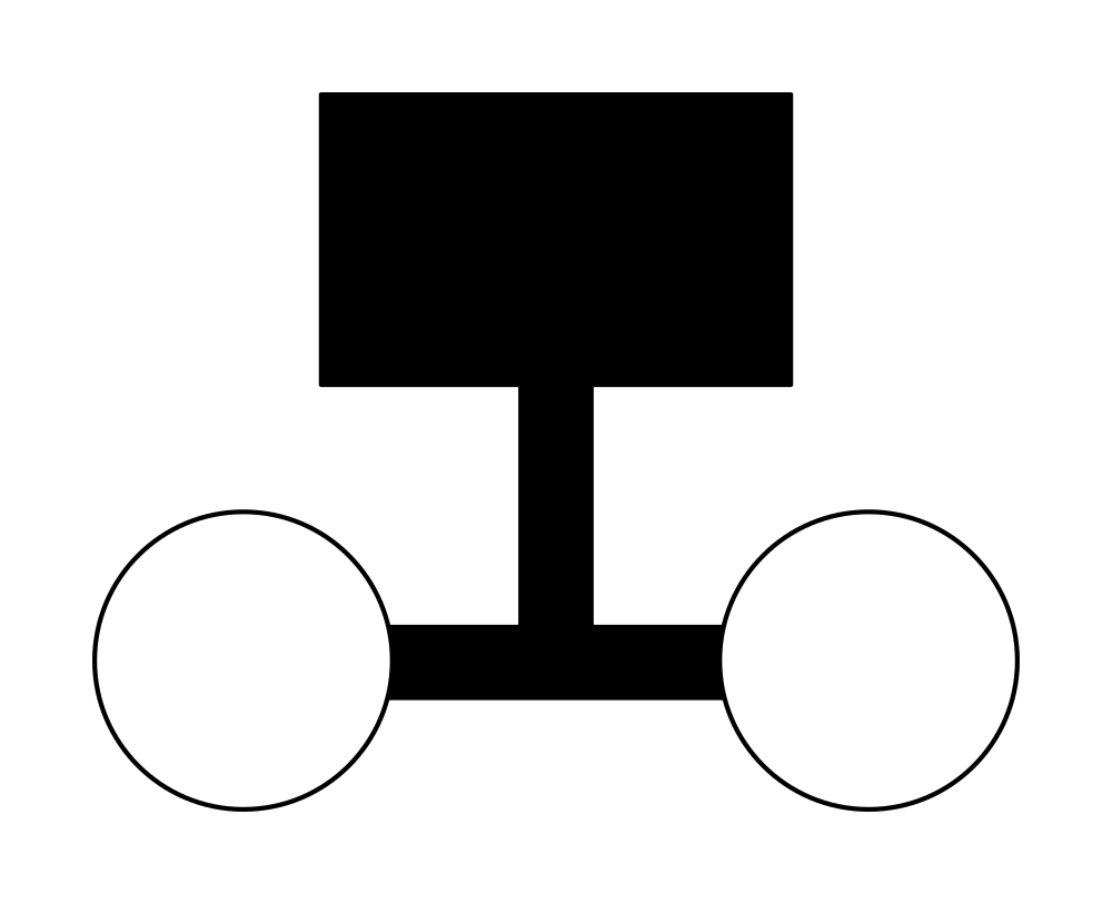
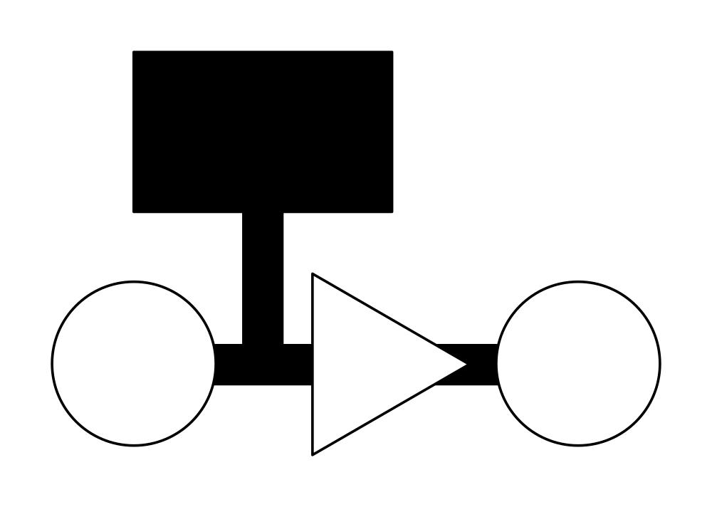
If you distort a gain stage, you effectively distort all following gain stages. That is, the sound of the clipping will be passed down the chain, even if no further clipping actually occurs. For this reason, avoid compensating for gain reduction at a point before the gain reduction goes into effect. Instead, compensate for gain reduction at a point AFTER the gain reduction has been applied. If your overall output level is insufficient, compensate for the problem as close to the system’s output side as is practicable.

With all that in your mind, it’s my view that you can handle just about any gain-structure problem that comes your way. Because these are concepts and NOT a procedure, most edge cases are handled automatically: If your usual routine results in one of the three needs not being met, you just make the changes necessary to get things back into alignment. Those changes are situationally dependent, and up to you.

Of course, some specifics would probably be nice, right?

The Preamp

First of all, I generally recommend forgetting about the idea of finding the “sweet spot” on a head amp/ mic pre/ whatever you want to call it. A preamp’s sweet spot is the point where its circuitry is becoming nonlinear with respect to the input. Some preamps just might impart that perfect hint of distortion that adds even-numbered harmonics to a signal, those harmonics being distributed such that the lows and low mids are emphasized “just so.”

They might.

If they’re the right mic pre and you get them set properly. Otherwise, the result will probably not be very nice.

If you really want to go off in pursuit of finding a preamp’s “magical gain setting of happiness,” and you have the time to do so, then go ahead. However, it seems to me that this nifty area of not-too-much-or-too-little nonlinearity is pretty small in comparison with the range where a preamp’s output is:

A) Linear with respect to the input, and

B) Allows the rest of the system’s controls to be run in a useful way.

As an audio-human who is generally WITHOUT the time necessary to chase down the preamp sweet spot on even one channel, and who is almost completely uninterested in running a mic pre in a range with significant nonlinearity anyway, I advise most people to just “get a decent input level and move on.” It’s much easier.

So – what’s a decent level, then?

Well, your numbers may vary. In my case, a preamp output signal that’s about 15 – 20 decibels below clipping is plenty. Because of the way the rest of the system is set up, preamp output at that level lets me run my faders and aux send pots in a convenient part of their travel, use everything else in its linear range, and gets me a long way above the electronic noise floor. (In other words, I satisfy all the conditions that I listed above).

Again, your specific number may vary, though I do certainly recommend setting up your system such that the area around 20 dB below clip is a workable preamp output level. This is a holistic sort of exercise, because everything depends on everything else. Let me explain.

Channel Faders And Knobs

Faders and aux-send knobs (ALSO faders, just rotary instead of linear) have one job: To allow you to conveniently set levels being sent to other destinations. Their ability to do this is directly tied to where your preamp output is, and it’s also tied to every other downstream gain stage. We’ll get to that in more detail – just be aware of it now.

If you’re running an honest-to-goodness pro-audio rig, the various incarnations of volume controls will be logarithmic in nature. That is, near the bottom of their travel, a small movement results in a large gain change. Near their maximum travel, that same amount of control movement results in a much smaller gain change. If the preamp output or console output gain is too high, you’ll find yourself pulling your faders and send knobs back so far that you can’t make “fine” adjustments very easily. If the upstream or downstream levels are too low, your controls may reach the end of their travel before you actually get enough acoustical output.

For the basic question of control usability, I find that a fader or knob that can run somewhere between its own -10 dB and 0 dB points is easily usable. In most cases, this gives me between 10 and 22 decibels of space to “get on the gas” if necessary, and the fader being relatively near its “unity” point means that a small movement doesn’t result in a wild change in level.

Beyond the basic question, though, lie the issues of repeatability and representation of proportion. Which gain stages do those things for you is a matter of personal preference and situational applicability.

Repeatability is the ease of placing multiple, comparable controls at the same setting, or placing one control at the same setting multiple times. There are certain cases where, for example, I want my vocal faders to reflect the basic, correct blend when they’re all at 0 dB. In that case, I will “mix with the preamps” to get an initial proportionality. The preamp gain-knob travels will be different from one another, reflecting the proportionality amongst channels, but the channel faders will be all the same. They won’t represent the proportion, but they are very easy to return to the baseline position. (This is also very handy when a mic is being shared amongst various applications. Getting it back to the right level for the main application is a snap.)

In lots of other situations, however, I tend to prefer a “same preamp gain, different fader position” approach. This is very handy for grab-n-go shows, because you know that channels with the same control positions applied are at the same gain. (Not the same output! The same gain.) This helps in terms of knowing where you are in regards to system instability and feedback. If the input gain on all comparable channels is the same, and things start to get “weird” at a certain point in fader travel on one channel, then things will probably get similarly troublesome for similar channels run with their faders at that level. In this case, the faders show the proportionality of total gain applied, and the preamps are in the more easily repeatable state.

The correct choice of which method to adopt is situationally dependent, as I said. I’ve already mentioned that I do both, although I use “repeatable preamp gain with proportional faders” much more often.

The way this relates to gain staging is that, with the approach where the preamps are repeated, you can end up with significantly “hotter” or “cooler” preamp output then you might otherwise have. If this results in clipping or level-control travel that’s tough to use, you have to rethink your strategy. However, especially for human voices, I have found that a certain overall setup will be right about 90% of the time. Those are pretty good odds.

For monitor world, I am becoming more and more enamored of proportionality on the send knobs with a global fader for trim. The first thing I do is to get things set so that, between a send knob at 0 dB and the global fader at “wherever,” the level is right for the main person needing that thing in the monitors. When that person is happy, I pretty much know for certain that the signal in question is audible through an on-deck wedge. If somebody else needs that channel in the monitors, I can quickly set their sends to 0 dB, which should result in basically the same per-wedge acoustical output as the first person is getting. From there, it’s easy to make fine adjustments as necessary. When done correctly, this results in on-the-fly monitor workflow which is very fast. (Please note that this is a pretty advanced application, requiring a separate or quasi-separate monitor world. I still thought I’d share it, though.)

Output Masters

When it comes to master outputs, I am a big fan of setting up the system’s holistic gain structure so that they can always be initially set at 0 dB, with the option to pull back if necessary. For me, repeatability is the main issue for master levels. I so rarely run into a situation where a mix even has a snowball’s chance of being “too quiet” that I simply don’t worry about the option of adding level at the console output.

This may not be the case for you, however. Where this can become a problem is when a console’s output master can go no higher than “unity gain” (0 dB). In this situation, it’s probably wise to rework the gain structure downstream from the console such that the mix master can be run at, say, -10 dB. Then you’ll have some ability to get louder as the situation dictates. Remember, the reason that I recommend focusing on the downstream (post) console gain structure for this is because “distortion flows downhill.” If you make up for a 10 dB master fader drop on the upstream side, you run a relatively substantial risk of clipping something in the process. The sound of that clipping (ickkkkk…) is passed downstream, all the way to the loudspeakers. By making up the gain on the downstream side, you have a much greater chance of keeping everything in its linear range. A bit more noise is greatly preferable to “crunch.”

No matter how things shake out in terms of control settings, I generally recommend running your console outputs with at least 10 dB of headroom to spare – 20 dB, if you can manage it. (Uncompressed peaks can be great big things.) Those numbers should be scaled appropriately if you’ve pulled the master output down for some reason. For instance, if the master has been pulled back 10 dB, you should ideally have 20 – 30 dB of headroom. If that’s not the case, you’re probably mixing too hot, and you should find a way to add output at a point that’s downstream of the console. You might not be clipping the console output, but you just might be cooking the snot out of the summing bus.

Sidenote: You’ve got to know what your metering is actually reading…

Post Console Processing

When it comes to things like equalizers and crossovers, I find that the repeatability issue takes great precedence. For this reason, I greatly prefer to run my “system drive” processing at unity gain. Please note, however, that an exception exists when you’ve pulled a console output master back so that you can get louder later. In that case, you will need to make up the lost gain somewhere.

As with everything else, you want to keep some headroom in your drive processing. Whatever the unit immediately preceding the amplifiers and loudspeakers is, it should be able to drive the amps into limit or clip without having to be clipped itself. At least 10 dB of headroom is desirable, if you can get it.

The Final Stage

The end of your gain chain is the amplifier. Whether that amplifier is fully exposed to you as an independent unit, or tucked away inside a loudspeaker enclosure with a whole bunch of invisible processing in front of it, the gain on and through the amp is the last piece of the puzzle.

For pro-audio power amps that exist as separate units, it’s very likely that unity input gain and maximum input gain are the same thing. You either pass the input signal straight through to the rest of the amp’s electronics, or you lug it down to some degree. For simplicity, repeatability, and protection against driving the upstream side into distortion, I recommend running amplifiers with their input attenuators wide open. Of course, you should NOT do this if it results in an undue amount of noise, or if it forces you to operate your console in an inconvenient way.

Most amplifiers these days have some sort of clip limiting which reduces (though it may not eliminate) audible distortion from a unit running at full tilt. It’s a very good practice to set up your rig such that the amps can be driven to maximum while everything else stays well within the range of linear operation: If the only system limiter you have is in the amplifier, that should be the only limiter you hit…and you should endeavor to engage that limiter as little as is possible. Not at all, if that’s realistic.

For powered speakers, the basic idea is the same. The upstream side should be able to drive the unit to full throttle without being at full throttle itself. The difference is that a powered speaker may have an input stage which allows for greater than unity gain to be applied to the downstream electronics.

If you do all this, and everything sounds good, but you still don’t have enough output, then there’s only one thing left to do. It’s the ultimate, “as far downstream as possible” makeup gain upgrade. You need to get your hands on more – or just plain louder – PA.


If you’re not completely burned out at this point, you can always go and read my article about the holistic nature of headroom