If you’re going to fix a problem, you have to know what the problem actually is.
Please Remember:
The opinions expressed are mine only. These opinions do not necessarily reflect anybody else’s opinions. I do not own, operate, manage, or represent any band, venue, or company that I talk about, unless explicitly noted.

 Want to use this image for something else? Great! Click it for the link to a high-res or resolution-independent version.
If you’re going to troubleshoot (and if you’re in the business of show production, troubleshooting is inevitable), there are two basic rules:
1) You have to know what the device is supposed to do.
2) You have to know how the device does what it’s supposed to do.
There are many layers of doing 1 and 2 effectively. The deeper you go, the more problem solving you can do. Gaining the knowledge required to peel back more and more layers is a long process. Decades long. I’ve had my hands in pro-audio since I was a teenager, and with about 20 years under my belt I’m finally starting to feel like I get what’s going on. In part, that’s because I’m getting more and more acquainted with the oceans of material I still don’t know. When you start to realize just how deep the rabbit hole is, you’ve been falling down that hole for a good while.
The above is a basic, foundational statement for this article, which is a follow-on to the opening “case study” from my previous post. After having a potential issue discussed with me, I ended up finding an alternate route to a solution. I took the different path because I had a suspicion that the problem wasn’t the voltage level of a pickup’s output. I figured that the real bugbear was that the voltage from the pickup was being transferred poorly, and also that the pickup’s bottom end was being lost. I considered this assumption as possible because I have a notion (not a truly detailed one, but a notion nonetheless) about how high-impedance pickups work. That is, I know that they can be reasonably modeled as a voltage source in series with a capacitance. This all comes together to form a device with a rather high output impedance in pro-audio terms. The issue with high-impedance outputs is that voltage transfer becomes non-trivial, and the issue with capacitors in series with voltage sources is that they create a high-pass filter.
Modeling Voltage Transfer With DC
For audio folks, what we’re interested in is voltage transfer. Even when amplifiers and loudspeakers are involved, and we become interested in power transfer, we achieve power transfer by way of voltage transfer. In many ways, effective voltage transfer is invisible to audio humans. It just sort of happens for us, because a lot of our gear is built to play nicely with a lot of other gear. At times, though, we’ll encounter gear that was NOT actually built to interface nicely with our existing equipment, and that can throw us for a loop. In the case of a high-impedance pickup interfaced with pro-audio inputs, we can get into a situation where we’re PILING on the gain, only to end up with a relatively weak signal. If we don’t know how the device does what it’s supposed to do, then we can start to assume that the voltage from the pickup is too low.
But that’s not the case. Piezo pickups – probably THE example of a high-output impedance device – make plenty of voltage. When mated to, say, a basic DI box, the problem is that the voltage doesn’t transfer. The input impedance of the mic pre is too low.
Before I go any further with this, I need to say something:
IMPORTANT – Audio circuits are NOT direct current. They are alternating current. Modeling an audio circuit via a DC example is not an entirely accurate picture of what’s happening. DC examples are simple to read and easy to “construct,” but they neither show the entire picture nor all the details of what’s happening.
With that in mind…
At a very basic level, the underlying issue with voltage transfer is that voltage drops when it travels across resistors. If we mentally model an audio circuit as a voltage source across one resistor (output impedance), and then have the remaining voltage travel across an additional load resistor (input impedance), we start to get a basic idea of how things can play out.
In our simplified, DC, everything-in-series circuit, the voltages across each resistor add up to the total voltage in the circuit. As such, the proportionality between the resistors representing output and input impedance matters a lot. If the output impedance is high in relation to the input impedance, a good deal of voltage will drop before ever getting a chance to drive the input. In the reverse case, only a small amount of the total voltage drops across the output impedance, allowing a healthy voltage transfer into the next part of the audio chain.
If I take a quick jaunt over to PartSim, I can build a quick ‘n dirty example circuit. This one represents one of my EV ND767a mics plugged into one of the preamps they usually “see,” which are on an M-audio Profire 2626. At a continuous level of 94 dB SPL (1 Pascal), an ND767a is rated for 3.1mV of RMS voltage output. That output can be modeled as being in series with a 300 ohm resistor. The mic-pre of the Profire can be modeled as a 3.7 kilohm resistor.
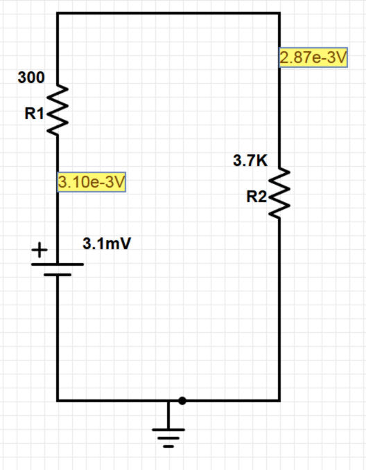
In this example, 0.23mV drops across the output impedance of the microphone. If you do the math to figure out the decibel loss, you find that about 0.67 dB was lost before the signal hit the mic pre. Even with this being a DC example, that number tracks very well with the output of the bridging calculator at Sengpiel Audio.
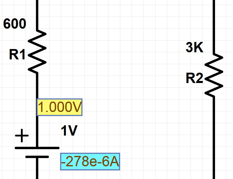
The above is an example of equipment that’s designed to interface nicely. What happens when a piezo pickup gets plugged into a basic DI box? That’s probably something like a 1 megohm output impedance being mated to a 50 kilohm input. The piezo can develop plenty of electrical potential. One volt RMS is +2.2 dBu, or definitely within the “line level” range. The voltage isn’t a problem at all, but the transfer of that voltage is a big deal.
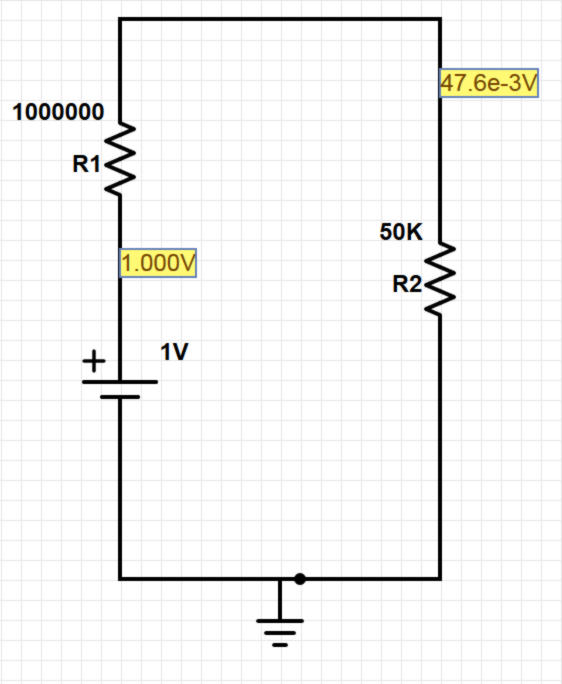
Immediately, 26 dB of voltage is dropped. If the DI box steps the voltage down even further (as is apt to happen), then the signal arriving at the console pre might be 46 dB down from the original voltage supplied by the pickup. The voltage arriving at the preamp is no higher than what you would get from a “hot output” dynamic mic in front of a not-too-loud source.
But Why Does It Sound So Bad?
Now then.
If the only real downside of our “not enough input impedance” situation was voltage loss, it wouldn’t be so bad. We’d have to run our preamps a little hot, but that’s hardly a dealbreaker.
The real awfulness comes about when the AC circuit issues enter into play. As I mentioned earlier, a piezo pickup in an audio circuit naturally tends to create a high-pass filter on its output. The high-pass filter becomes less audible as the load (input) impedance goes up. The problem, then, is that a too-small load impedance causes a very marked loss of low-frequency information. The pickup sounds “clanky” or “nasal,” because all of its really usable output becomes restricted to the high-frequency part of the audio passband.
Here’s a simplified model of a piezo pickup connected to a 50 kilohm DI box. I haven’t tried to fully represent the output impedance of the pickup, so the voltage numbers won’t be right. I used a 650 pF capacitor to represent the pickup, because the simulation of the circuit with that capacitance seems to basically represent what I’ve observed in the field.
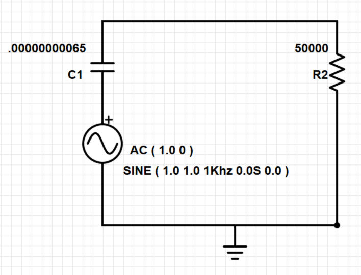

At 1 kHz, the signal is about 13 dB down from the maximum level. At 200 Hz the signal is down 27 dB. Good luck correcting that with any bog-standard EQ you have handy.
Compare that with what happens when the load impedance is 1 megohm, which is what some of my active DI boxes are rated for:
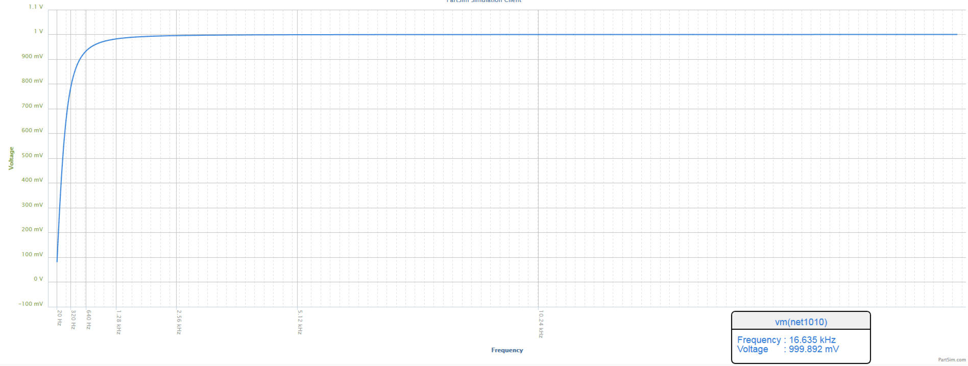
Yes, there’s still a highpass filter in effect. Even so, it’s rather less terrifying. The filter’s 3 dB down point happens at about 250 Hz, and you’re only about 8 dB down at 100 Hz. That’s hardly perfect, but it’s manageable. (A DI box or preamp with a 10 megohm input impedance basically makes the low frequency loss a non-issue.)
Once more, I need to emphasize that these are simple models. They won’t exactly represent what you run into during the course of setting up an actual show.
But they do show that the voltage generated by a troublesome audio source is not necessarily the root of a given problem. Poor voltage transfer and circuits that mess with frequency response (when presented with a small load impedance) may be what’s really hurting you.