Tag Archives: Experimentation

In Defense Of Smoothing Your Traces

In the end, you have to be able to read a graph for the graph to be useful.

Please Remember:

The opinions expressed are mine only. These opinions do not necessarily reflect anybody else’s opinions. I do not own, operate, manage, or represent any band, venue, or company that I talk about, unless explicitly noted.

Want to use this image for something else? Great! Click it for the link to a high-res or resolution-independent version.

There are people out there who insist that, when measuring an audio system, you should never smooth the trace. The argument is that you might miss some weird anomaly that gets filtered out by the averaging – and, in any case, the purpose of graphing a transfer function isn’t for the picture to look nice.

I think that’s an understandable sentiment, especially because it’s a thought uttered by people who I think are knowledgeable, respectable, and worth working alongside. At the same time, though, I can’t fully embrace their thinking. I very regularly apply 1/6th octave smoothing to measurements, and I do it for a very specific reason: I do indeed want to see the anomalies that matter, and I need to be able to clearly contextualize them.

The featured image on this article is an example of why I think the way I do. I’ve got a bit of a science-project going, and part of that project involved measuring a Yamaha DBR12. The traces you see in the picture are the same measurement, with the bottom one being smoothed. The unsmoothed trace is very hard to read for all the visual noise it presents, which makes it difficult to make any sort of decision about what corrections to make. the smoothed trace gives me a lot more to go on. I can see that 90 Hz – 150 Hz could come down a bit, with 2 kHz – 7.5 kHz maybe needing a bit of a bump to achieve maximum flatness.

So, I say, smooth those traces…but don’t oversmooth them! You want to suppress the information overload without losing the ability to find things that stand out. The 1/6th octave option seems to be the right compromise for me, with 1/12th still being more detail than is useful and 1/3rd getting into the area where too much gets lost.

And here’s another wrinkle: I support unsmoothed traces when you’re measuring devices that ignore acoustics, like the transfer function of a mixing console from input to output. In such a case, you should expect a very, very linear transfer function, and so the ability to spot tiny deviations is a must. The difficulty is when you’re in a situation where there a gazillion deviations, and they all appear significant. In such a case, which I’ve found to be the norm for measurements that involve acoustics, filtering to find what’s actually significant to the operation of an audio system is helpful.


Start From The Top

When working on mixing a “bass” instrument, don’t necessarily start with the low frequency information.

Please Remember:

The opinions expressed are mine only. These opinions do not necessarily reflect anybody else’s opinions. I do not own, operate, manage, or represent any band, venue, or company that I talk about, unless explicitly noted.

Want to use this image for something else? Great! Click it for the link to a high-res or resolution-independent version.

Whenever I have a problem (that is genuinely my problem and not because of the instrument or player) where a bass guitar, kick drum, or other “LF” instrument is just a pile of boom or indistinct rumble, it’s often because I failed to “start from the top.”

Or, the middle at least.

You see, it’s not really all about that bass. I’ve said many times that low-frequency information IS important and part of “the fun,” and that hasn’t changed for me. In truth, though, a mix stands or falls on the absolutely critical midrange (where almost all the musical information actually sits). It’s my very strong opinion that the midrange information, then, should be what you start with whenever possible. The “impact” of a kick drum? The sound that makes that giant percussion instrument sound like it’s aggressive and smashed against your nose? That’s almost always high-mid information and up. The definition and character of a bass guitar that really gives it the ability to speak in a musical way? Low-mids and up.

So, I say to you, get those areas right first. Yank down your aux-fed-sub drive sends and roll those channel HPF filters up. Use a low-shelf EQ as a sledgehammer if necessary. Especially do this, and do it more aggressively if you’re starting from what sounds like a muddy mess. Then, start pushing that fader upwards. You may need to run your preamp or trim level a bit hotter than you’re used to, but eventually, you should find a place where what’s still passing through ends up dropping into place with the rest of the band. If you’re just listening to one channel at a time, then you can ballpark yourself by finding a satisfying blend with the wash coming off the deck.

After that’s done, THEN start letting some bass frequencies through. You may find that you need a lot less LF than you first thought, especially if you were driving the deep-down sound hard in an effort to hear the instrument in question. I find it quite trivial to create a whole maelstrom of booming slop if I’m using the subwoofers to push something like a kick drum into the right place against everything else, but I find it much harder to make a mess if I park the “click” in a handy place, and then gently move the bottom into alignment afterwards.

It’s a bit counter intuitive, I know, but I can’t remember a time where I put the mids and highs under a microscope first and ended up with a result I disliked. At the same time, I can easily remember all kinds of situations where I didn’t, and subsequently backed myself into a terrible-sounding corner by starting with a bunch of unreadable low end.

Oh, and here’s a postscript bombshell for you: I have a sneaky suspicion that, for many engineers, the subwoofers they end up saying are the punchiest are actually very similar to other offerings in the general class. My guess is that the REAL difference was how the full-range PA mated with those subs, and that’s what got their attention.


Micing A Saw

Contact transducers are really nifty, but take some doing to use.

Please Remember:

The opinions expressed are mine only. These opinions do not necessarily reflect anybody else’s opinions. I do not own, operate, manage, or represent any band, venue, or company that I talk about, unless explicitly noted.

Want to use this image for something else? Great! Click it for the link to a high-res or resolution-independent version.

You may eventually be asked to transduce the noises produced by a saw. I’m not talking about sound effects for film, here. I’m talking about music. A handsaw with a sufficiently manipulable blade can be played very effectively with a violin bow. The resulting emanations are what I would call “a wood-shop Theremin.”

I have effectively captured these sonic events with regular microphones. As with anything else, a unit that basically sounds like the thing it’s pointed at will generally be fine. The troublesome element really is that saws don’t have the kind of body that creates a lot of output. Their resulting lack of SPL can pose a challenge when they’re put into an ensemble, because almost anything else is going to be much, much louder.

As a result of the above, I have, (for years) wanted to try using a contact transducer on a musical saw. I finally got my chance a couple of weeks ago. I was very pleased with the outcome, because I could actually hear some of what the saw was doing in the context of a very busy band.

The key to the whole thing was a Dean Markley Artist Transducer. It’s essentially a gussied-up piezo, with the element potted in some kind of polymer that sits in a wooden surround. The bottom of the pickup has that poster-tack Silly Putty applied, so you can temporarily stick the thing to a surface. As with any piezo-based transducer, you’ll want to connect it through an active DI box; The ultra-high impedance of the op-amp will stop you from loading down the pickup.

Contact micing lives and dies on placement, even more so than regular microphones. Parking the transducer in a bad spot can get you very strange results, but there’s more to the story: The pickup’s physical contact changes the vibrational behavior of the surface that it’s connected to. As such, you want to find a spot where you’ll get good transfer of the instrument’s movement, while avoiding a placement that dampens that same vibration. With a saw, that means that you’ll probably want to search for a place that’s as close to the handle as possible. This serves the dual purpose of keeping the transducer and cable out of the way, while also allowing the blade to move freely.

You will also want to make sure that you have the ability to DRASTICALLY reduce the high-frequency output of the saw channel. (A freely sweepable low-pass filter is the best case.) I’m starting to form a theory that vibrating surfaces and air create a sort of acoustical inductor – a device that impedes high-frequency output. Take away the transition to air-carried waves, and a lot of information that you’re not used to hearing comes into play. The bow scraping against the blade is hard to hear with traditional micing, but a contact mic really brings that sound through. We ended up rolling the filter down rather far…like, 1 kHz far, before a result was created that wasn’t too jarring.

All of this takes some work and planning, certainly, but the end result of much, much, MUCH improved gain-before-feedback can be tremendously helpful. Consider getting a contact transducer for your box-of-goodies. It might prove to be a highly handy tool one day.


Graphic Content

Transfer functions of various reasonable and unreasonable graphic EQ settings.

Please Remember:

The opinions expressed are mine only. These opinions do not necessarily reflect anybody else’s opinions. I do not own, operate, manage, or represent any band, venue, or company that I talk about, unless explicitly noted.

Want to use this image for something else? Great! Click it for the link to a high-res or resolution-independent version.

An aphorism that I firmly believe goes like this: “If you can hear it, you can measure it.” Of course, there’s another twist to that – the one that reminds you that it’s possible to measure things you can’t hear.

The graphic equalizer, though still recognizable, is losing a bit of its commonality as an outboard device. With digital consoles invading en masse, making landings up and down the treasure-laden coasts of live audio, racks and racks of separate EQ devices are being virtualized inside computer-driven mix platforms. At the same time, hardware graphics are still a real thing that exists…and I would wager that most of us haven’t seen a transfer function of common uses (and abuses) of these units, which happen whether you’ve got a physical object or a digital representation of one.

So – let me dig up a spare Behringer Ultragraph Pro, and let’s graph a graphic. (An important note: Any measurement that you do is a measurement of EXACTLY that setup. Some parts of this exercise will be generally applicable, but please be aware that what we’re measuring is a specific Behringer EQ and not all graphic EQs in the world.)

The first thing to look at is the “flat” state. When you set the processing to “out,” is it really out?

In this case, very much so. The trace is laser flat, with +/- 0.2 dB of change across the entire audible spectrum. It’s indistinguishable from a “straight wire” measurement of my audio interface.

Now, we’ll allow audio to flow through the unit’s filtering, but with the high and low-pass filters swept to their maximums, and all the graph filters set to 0 dB.

The low and high-pass filters are still definitely having an effect in the audible range, though a minimal one. Half a decibel down at 45 Hz isn’t nothing, but it’s also pretty hard to hear.

What happens when the filters are swept to 75 Hz and 10 kHz?

The 3dB points are about where the labeling on the knobs tells you it should be (with a little bit of overshoot), and the filters roll off pretty gently (about 6 dB per octave).

Let’s sweep the filters out again, and make a small cut at 500 Hz.

Interestingly, the filter doesn’t seem to be located exactly where the faceplate says it should be – it’s about 40% of a third-octave space away from the indicated frequency center, if the trace is accurate in itself.

What if we drop the 500 Hz filter all the way down, and superimpose the new trace on the old one?

The filter might look a bit wider than what you expected, with easily measurable effects happening at a full octave below the selected frequency. Even so, that’s pretty selective compared to lots of wide-ranging, “ultra musical” EQ implementations you might run into.

What happens when we yank down two filters that are right next to each other?

There’s an interesting ripple between the cuts, amounting to a little bit less than 1 dB.

How about one of the classic graphic EQ abuses? Here’s a smiley-face curve:

Want to destroy all semblance of headroom in an audio system? It’s easy! Just kill the level of the frequency range that’s easiest to hear and most efficient to reproduce, then complain that the system has no power. No problem! :Rolls Eyes:

Here’s another EQ abuse, alternately called “Death To 100” or “I Was Too Cheap To Buy A Crossover:”

It could be worse, true, but…really? It’s not a true substitute for having the correct tool in the first place.


The Lessons Of El Ridiculoso

Loudspeaker experiments are very educational.

Please Remember:

The opinions expressed are mine only. These opinions do not necessarily reflect anybody else’s opinions. I do not own, operate, manage, or represent any band, venue, or company that I talk about, unless explicitly noted.

Want to use this image for something else? Great! Click it for the link to a high-res or resolution-independent version.

El Ridiculoso is an idea that’s been bumping around in my head – conceptualized in various morphologies – for years. With the help of the extravagantly cool Mario Caliguiri, who does custom woodworking out here in the high desert, the idea is now incarnated.

Inwoodnated.

Inwoodnated is a real word, because I made it up. All words are made up.

Anyway…

El Ridiculoso is a quad-amped monstrosity meant to go “pretty loud” (but not insanely loud) with 2300 watts of peak input creating about 131 dB of peak, 1 meter SPL. It is very definitely NOT meant to play down low. The conveniently-sized, sealed box for the 15″ driver starts rolling off somewhere around 75 Hz, and really, El Ridiculoso is supposed to be used with subwoofers carrying everything up to 100 Hz anyway. (Sealed boxes are easier to build, and generally pretty forgiving. You can “fudge” the internal volume a bit and still have the whole driver-and-box system work pretty well.)

A few days ago, I got to hook amplifiers up to the boxes and hear them make noise. I found the experience to be rather educational in a few areas.

If You Tune It By Ear You Will Probably Get It Wrong

I set up an X32 mixing console to act as a four-way crossover: You downmix two channels to the main bus, and then send the main bus to matrices 1-4. (The matrices have crossover filters available to them if you have the right firmware upgrade in place.) Because I wouldn’t be working with subwoofers for the test run, I started off by putting the 15’s high-pass at 75 Hz, with the low-pass at 400 Hz. The 12 handled 400 – 1600, the big horn did 1600 – 6400, and the smaller horn took everything above that.

And, of course, I started out by playing music and pushing the different bandpass levels around.

I ended up with an overall sound that was reasonably pleasing, but somewhat tubby (or resonant) at certain bass frequencies. I wondered if the 15’s box was booming for some reason – maybe it was acting like a drum?

In any case, I decided it was time to do some measuring for a real, honest-to-goodness magnitude line-up of the boxes. As I started running sweeps and making adjustments, one thing became VERY clear: Tuning the system by ear had sent me way off course. In some cases, 10+ dB off course. (!)

A Basic Bandpass Magnitude Alignment Fixes A Lot

When you’ve missed the mark as far as I had, information that should blend nicely with other information…doesn’t. You get things like overpowering bass notes, because the crucial midrange just isn’t there to balance it all out. I was actually pretty stunned at just how much better the stack sounded with all the boxes in basically the right place, volume-wise. The music I was playing suddenly started to have the tonal characteristics I’d grown used to from listening at home.

This was without any corrective EQ, which is what I worked on next.

Going through and getting a fine-detail equalization solution certainly changed things, but the difference was not nearly as pronounced as what had happened before. This surprised me as well. I had expected that applying the “make-em-really-flat” solution would result in a massive change in clarity, but really, we were most of the way there already.

Large Horns Make Large Noise

I discovered rather quickly that sitting with my head right up against the 2″ driver-exit horn was unpleasant. The amount of noise that thing can make is impressive. The matrix feed to that bandpass ended up being 12 dB down from everything else, and I still preferred being across the room. I’ve known for years – at an academic level – that 2″ exit compression drivers are used when you need to tear faces off, but this was the first time that I even got a whiff of what they’re really capable of.

Awesome But Impractical

Playing with El Ridiculoso is a great treat, but I can’t imagine getting three more built for regular gigs. For a start, they’re relatively complicated to set up, because all the bandpasses are in separate enclosures…and there are four bandpasses per speaker system. Big-boy loudspeakers might have three bandpasses, but they package them all into a single cabinet. Plus, you usually get one Speakon connector which you can use to mate all your power channels to all your drivers in one click. El Ridiculoso needs four separate connections to work.

Add to that the need for subwoofers in many cases, and now you’ve got a five-way system. Then you have to add all the amplifiers necessary, and all the crossovers/ system management, which results in a pretty hefty drive rack or two. Then you have to add all the speaker cable. You end up spending a lot of money, and a lot of weight, just to make the things work.

And, the only way to get them up in the air is scaffolding, or stacking them on a big pile of subs.

In the end, a compact, ultra-engineered box from a major manufacturer really has the advantage. El Ridiculoso sure does have a lot of “cool factor” as an exotic idea, but a good, solid, self-powered biamp unit will go just about as loud and require far less care and feeding to be day-to-day useful.

This doesn’t mean I’m sad about the experiment. I knew from the beginning that I wasn’t going to design a better mousetrap than every speaker manufacturer on the planet. What I wanted is what I got: A different implementation that I could use to get more hands-on understanding of how these things work.


The Grand Experiment

A plan for an objective comparison of the SM58 to various other “live sound” microphones.

Please Remember:

The opinions expressed are mine only. These opinions do not necessarily reflect anybody else’s opinions. I do not own, operate, manage, or represent any band, venue, or company that I talk about, unless explicitly noted.

Want to use this image for something else? Great! Click it for the link to a high-res or resolution-independent version.

Purpose And Explanation

Ever since The Small Venue Survivalist became a reality, I have wanted to do a big experiment. I’ve been itching to round up a bunch of microphones that can be purchased for either below, or slightly above the price point of the SM58, and then to objectively compare them to an SM58. (The Shure SM58 continues to be an industry standard microphone that is recognized and accepted everywhere as a sound-reinforcement tool.)

The key word above is “objectively.” Finding subjective microphone comparisons isn’t too hard. Sweetwater just put together (in 2017) a massive studio-mic shootout, and it was subjective. That is, the measurement data is audio files that you must listen to. This isn’t a bad thing, and it makes sense for studio mics – what matters most is how the mic sounds to you. Listening tests are everywhere, and they have their place.

In live audio, though, the mic’s sound is only one factor amongst many important variables. Further, these variables can be quantified. Resistance to mechanically-induced noise can be expressed as a decibel number. So can resistance to wind noise. So can feedback rejection. Knowing how different transducers stack up to one another is critical for making good purchasing decisions, and yet this kind of quantitative information just doesn’t seem to be available.

So, it seems that some attempt at compiling such measurements might be helpful.

Planned Experimental Procedure

Measure Proximity Effect

1) Generate a 100Hz tone through a loudspeaker at a repeatable SPL.

2) Place the microphone such that it is pointed directly at the center of the driver producing the tone. The front of the grill should be 6 inches from the loudspeaker baffle.

3) Establish an input level from the microphone, and note the value.

4) Without changing the orientation of the microphone relative to the driver, move the microphone to a point where the front of the grill is 1 inch from the loudspeaker baffle.

5) Note the difference in the input level, relative to the level obtained in step 3.

Assumptions: Microphones with greater resistance to proximity effect will exhibit a smaller level differential. Greater proximity effect resistance is considered desirable.

Establish “Equivalent Gain” For Further Testing

1) Place a monitor loudspeaker on the floor, and position the microphone on a tripod stand. The stand leg nearest the monitor should be at a repeatable distance, at least 1 foot from the monitor enclosure.

2) Set the height of the microphone stand to a repeatable position that would be appropriate for an average-height performer.

3) Changing the height of the microphone as little as possible, point the microphone directly at the center of the monitor.

4) Generate pink-noise through the monitor at a repeatable SPL.

5) Using a meter capable of RMS averaging, establish a -40 dBFS RMS input level.

Measure Mechanical Noise Susceptibility

1) Set the microphone such that it is parallel to the floor.

2) Directly above the point where the microphone grill meets the body, hold a solid, semi-rigid object (like an eraser, or small rubber ball) at a repeatable distance at least 1 inch over the mic.

3) Allow the object to fall and strike the microphone.

4) Note the peak input level created by the strike.

Assumptions: Microphones with greater resistance to mechanically induced noise will exhibit a lower input level. Greater resistance to mechanically induced noise is considered desirable.

Measure Wind Noise Susceptibility

1) Position the microphone on the stand such that it is parallel to the floor.

2) Place a small fan (or other source of airflow which has repeatable windspeed and air displacement volume) 6 inches from the mic’s grill.

3) Activate the fan for 10 seconds. Note the peak input level created.

Assumptions: Microphones with greater resistance to wind noise will exhibit a lower input level. Greater resistance to wind noise is considered desirable.

Measure Feedback Resistance

1) Set the microphone in a working position. For cardioid mics, the rear of the microphone should be pointed directly at the monitor. For supercardioid and hypercardioid mics, the the microphone should be parallel with the floor.

2a) SM58 ONLY: Set a send level to the monitor that is just below noticeable ringing/ feedback.

2b) Use the send level determined in 2a to create loop-gain for the microphone.

3) Set a delay of 1000ms to the monitor.

4) Begin a recording of the mic’s output.

5) Generate a 500ms burst of pink-noise through the monitor. Allow the delayed feedback loop to sound several times.

6) Stop the recording, and make note of the peak level of the first repeat of the loop.

Assumptions: Microphones with greater feedback resistance will exhibit a lower input level on the first repeat. Greater feedback resistance is considered desirable.

Measure Cupping Resistance

1) Mute the send from the microphone to the monitor.

2) Obtain a frequency magnitude measurement of the microphone in the working position, using the monitor as the test audio source.

3) Place a hand around as much of the mic’s windscreen as is possible.

4) Re-run the frequency magnitude measurement.

5) On the “cupped” measurement, note the difference between the highest response peak, and that frequency’s level on the normal measurement.

Assumptions: Microphones with greater cupping resistance will exhibit a smaller level differential between the highest peak of the cupped response and that frequency’s magnitude on the normal trace. Greater cupping resistance is considered desirable.


THD Troubleshooting

I might have discovered something, or I might not.

Please Remember:

The opinions expressed are mine only. These opinions do not necessarily reflect anybody else’s opinions. I do not own, operate, manage, or represent any band, venue, or company that I talk about, unless explicitly noted.

Want to use this image for something else? Great! Click it for the link to a high-res or resolution-independent version.

Over the last little while, I’ve done some shows where I could swear that something strange was going on. Under certain conditions, like with a loud, rich vocal that had nothing else around it, I was sure that I could hear something in FOH distort.

So, I tried soloing up the vocal channel in my phones. Clean as a whistle.

I soloed up the the main mix. That seemed okay.

Well – crap. That meant that the problem was somewhere after the console. Maybe it was the stagebox output, but that seemed unlikely. No…the most likely problem was with a loudspeaker’s drive electronics or transducers. The boxes weren’t being driven into their limiters, though. Maybe a voice coil was just a tiny bit out of true, and rubbing?

Yeesh.

Of course, the very best testing is done “In Situ.” You get exactly the same signal to go through exactly the same gear in exactly the same place. If you’re going to reproduce a problem, that’s your top-shelf bet. Unfortunately, that’s hard to do right in the middle of a show. It’s also hard to do after a show, when Priority One is “get out in a hurry so they can lock the facility behind you.”

Failing that – or, perhaps, in parallel with it – I’m becoming a stronger and stronger believer in objective testing: Experiments where we use sensory equipment other than our ears and brains. Don’t get me wrong! I think ears and brains are powerful tools. They sometimes miss things, however, and don’t natively handle observations in an analytical way. Translating something you hear onto a graph is difficult. Translating a graph into an imagined sonic event tends to be easier. (Sometimes. Maybe. I think.)

This is why I do things like measure the off-axis response of a cupped microphone.

In this case, though, a simple magnitude measurement wasn’t going to do the job. What I really needed was distortion-per-frequency. Room EQ Wizard will do that, so I fired up my software, plugged in my Turbos (one at a time), and ran some trials. I did a set of measurements at a lower volume, which I discarded in favor of traces captured at a higher SPL. If something was going to go wrong, I wanted to give it a fighting chance of going wrong.

Here’s what I got out of the software, which plotted the magnitude curve and the THD curve for each loudspeaker unit:

I expected to see at least one box exhibit a bit of misbehavior which would dramatically affect the graph, but that’s not what I got. What I can say is that the first measurement’s overall distortion curve is different, lacking the THD “dip” at 200 Hz that the other boxes exhibit, significantly more distortion in the “ultra-deep” LF range, and with the “hump” shifted downwards. (The three more similar boxes center that bump in distortion at 1.2 kHz. The odd one out seems to put the center at about 800 Hz.)

So, maybe the box that’s a little different is my culprit. That’s my strong suspicion, anyway.

Or maybe it’s just fine.

Hmmmmm…


How Much Light For Your Dollar?

Measurements and observations regarding a handful of relatively inexpensive LED PARs.

Please Remember:

The opinions expressed are mine only. These opinions do not necessarily reflect anybody else’s opinions. I do not own, operate, manage, or represent any band, venue, or company that I talk about, unless explicitly noted.

box_of_lightsWant to use this image for something else? Great! Click it for the link to a high-res or resolution-independent version.

I’m in the process of getting ready for a pretty special show. The album “Clarity” by Sons Of Nothing is turning 10, and a number of us are trying to put together one smasher of a party.

Of course, that means video.

And our master of all things videographic is concerned about having enough light. We can’t have anybody in the band who’s permanently stuck in “shadow.” You only get one chance to shoot a 10th anniversary concert, and we want to get it right.

As such, I’m looking at how to beef up my available lighting instruments. It’s been a long while since I’ve truly gone shopping for that old mainstay of small-venue lighting, the LED wash PAR, but I do take a look around every so often. There’s a lot to see, and most of it isn’t very well documented. Lighting manufacturers love to tell you how many diodes are in a luminaire, and they also like to tell you how much power the thing consumes, but there appears to be something of an allergy to coughing up output numbers.

Lux, that is. Lumens per square meter. The actual effectiveness of a light at…you know…LIGHTING things.

So, I thought to myself, “Self, wouldn’t it be interesting to buy some inexpensive lights and make an attempt at some objective measurement?”

I agreed with myself. I especially agreed because Android 4.4 devices can run a cool little Google App called “Science Journal.” The software translates the output from a phone’s ambient light sensor into units of lux. For free (plus the cost of the phone, of course). Neat!

I got onto Amazon, found myself a lighting brand (GBGS) that had numerous fixtures available for fulfillment by Amazon, and spent a few dollars. The reason for choosing fulfillment from Amazon basically comes down to this: I wanted to avoid dealing with an unknown in terms of shipping time. Small vendors can sometimes take a while to pack and ship an order. Amazon, on the other hand, is fast.

The Experiment

Step 1: Find a hallway that can be made as dark as possible – ideally, dark enough that a light meter registers 0 lux.

Step 2: At one end, put the light meter on a stand. (A mic stand with a friction clip is actually pretty good at holding a smartphone, by the way.)

Step 3: At the other end, situate a lighting stand with the “fixture under test” clamped firmly to that stand.

Step 4: Measure the distance from the lighting stand to the light meter position. (In my case, the distance was 19 feet.)

Step 5: Darken the hallway.

Step 6: Set the fixture under test to maximum output using a DMX controller.

Step 7: Allow the fixture to operate at full power for roughly 10 minutes, in case light output is reduced as the fixture’s heat increases.

Step 8: Ensure the fixture under test is aimed directly at the light meter.

Step 9: Note the value indicated by the meter.

Important Notes

A relatively long distance between the light and the meter is recommended. This is so that any positioning variance introduced by placing and replacing either the lights or the meter has a reduced effect. At close range, a small variance in distance can skew a measurement noticeably. At longer distances, that same variance value has almost no effect. A four-inch length difference at 19 feet is about a 2% error, whereas that same length differential at 3 feet is an 11% error.

It’s important to note that the hallway used for the measurement had white walls. This may have pushed the readings higher, as – similarly to audio – energy that would otherwise be lost to absorption is re-emitted and potentially measurable.

It was somewhat difficult to get a “steady” measurement using the phone as a meter. As such, I have estimated lux readings that are slightly lower than the peak numbers I observed.

These fixtures may or may not be suitable for your application. These tests cannot meaningfully speak to durability, reliability, acceptability in a given setting, and so on.

The calculation for 1 meter lux was as follows:

19′ = 5.7912 m

5.7912 = 2^2.53 (2.53 doublings of distance from 1m)

Assumed inverse square law for intensity; For each doubling of distance, intensity quadruples.

Multiply 19′ lux by 4^2.53 (33.53)

Calculated 1 meter lux values are just that – calculated. LED PAR lights are not a point-source of light, and so do not behave like one. It requires a certain distance from the fixture for all the emitters to combine and appear as though they are a single source of light.

The Data

The data display requires Javascript to work. I’m sorry about that – I personally dislike it when sites can’t display content without Javascript. However, for the moment I’m backed into a corner by the way that WordPress works with PHP, so Javascript it is.


Ascending sort by:


Knowledge VS Wisdom

You can know the terminology and not know what you’re doing.

Please Remember:

The opinions expressed are mine only. These opinions do not necessarily reflect anybody else’s opinions. I do not own, operate, manage, or represent any band, venue, or company that I talk about, unless explicitly noted.

knowledge-and-wisdomWant to use this image for something else? Great! Click it for the link to a high-res or resolution-independent version.
Regarding the above picture, I got the Kanji for knowledge and wisdom from Google. At least, I think that’s what I got. The above might actually read, “Your mother is a recalcitrant platypus,” but I wouldn’t know.

Anyway…

I’m pretty confident that any average, adult human can be taught in less than one hour everything necessary to operate a parametric EQ.

I did not say that they would operate it well, or appropriately. Throwing them onto a stage-side monitor console to run rock-n-roll wedges in real time would probably be a very poor move. The process of you getting fired would be legendary.

The problem isn’t knowledge, especially now that many of us carry devices capable of accessing vast reserves of information by way of wireless data. The problem is wisdom born of experience. The way that you get good at wielding all manner of EQ implementations against all manner of audio goblins is by wielding EQ against audio goblins. There’s no substitute for it. Encountering problems, making changes, and hearing the results of those changes immediately is how learning takes place.

I do urge people to learn the vocabulary and the concepts. I wouldn’t spend so much time pushing math, science, and applied audio nerdery on this site if I felt differently. Knowing the words and the numbers allows you to do (at least) two things: First, you can put names and values on both problems and solutions, and second, with that ability you can then ask better questions. The heart of all engineering – that is, the application of mathematical, scientific, and logical processes to the solving of puzzles – is the asking and answering of a series of questions. The questions can be abstract or concrete. They can be theoretical, or relating to something happening in the here and now. The circumstances hardly matter; Better questions return better answers.

But if all you do is memorize the words and ideas without getting your “fubs” on them in real life, your application of the concepts will be stunted. It’s a bit like this gem from Tom Roche, written down on Pro Sound Web’s LAB Basement Forum: “As I understand it, knowledge is knowing that a tomato is a fruit. Wisdom is not putting it in a fruit salad.”

There are lots of guys and gals out there who know everything there is to know about metaphorical tomatoes, and yet make terrible, metaphorical fruit salads. Folks who can name every knob and switch on a console, yet seemingly can’t hear that their mix is all drums and barely any vocal. People who talk about audio concepts using words that you definitely recognize, yet it’s all strung together in ways that are nonsensical. Craftspersons who memorized a workflow without knowing why it worked in the first place, and who get completely wrecked when the situation calls for something different.

More knowledge is good, but there’s a point where you can no longer read your way through problem solving. At some point, the book has to be set down and some knobs turned. That’s where most of the fun is, anyway.


Double Hung Discussion

It’s not magic, and it may not be for you. It works for me, though.

Please Remember:

The opinions expressed are mine only. These opinions do not necessarily reflect anybody else’s opinions. I do not own, operate, manage, or represent any band, venue, or company that I talk about, unless explicitly noted.

double-hungWant to use this image for something else? Great! Click it for the link to a high-res or resolution-independent version.

On the heels of my last article, it came to may attention that some folks were – shall we say – perplexed about my whole “double hung” PA deployment. As can be the case, I didn’t really go into any nuance about why I did it, or what I expected to get out of it. This lead some folks to feel that it was a really bizarre way to go about things, especially when a simpler solution might have been a better option.

The observations I became aware of are appropriate and astute, so I think it’s worth talking about them.

Why Do It At All?

First, we can start with that logistics thing again.

When I put my current system together, I had to consider what I was wanting to do. My desire was to have a compact, modular, and flexible rig that could “degrade gracefully” in the event of a problem. I also had no desire to compete with the varsity-level concert systems around town. To do so would have required an enormous investment in both gear and transport, one that I was unwilling (and unable) to make.

What I’ve ended up with, then, is a number of smaller boxes. If I need more raw output, I can arrange them so that they’re all hitting the same general area. I also have the option of deploying for a much wider area, but with reduced total output capability. I wouldn’t have that same set of options with a small number of larger, louder enclosures.

That’s the basic force behind why I have the rig that I have. Next come the more direct and immediate issues.

The first thing is just a practical consideration: Because my transport vehicle isn’t particularly large, I don’t really have the necessary packing options required to “leave gear on the truck.” If I’m getting the rig out, I might as well get all of it out. This leads to a situation where I figure that I might as well find a way to deploy everything all the time. The gear is meant to make noise, not sit around. “Double hung” lets me do that in a way that makes theoretical sense (I’ll say more on why in a bit).

The second reason is less practical. I have a bit of a penchant for the unconventional and off-the-wall. I sometimes enjoy experiments for the sake of doing them, and running a double hung system is just that kind of thing. I like doing it to find out what it’s like to do it.

Running double hung is NOT, by any means, more practical than other deployments. Especially if you’re new to this whole noise-louderization job, going with this setup is NOT some sort of magical band-aid that is going to fix your sound problems. Also, if you’re getting good results with a much simpler way of doing things, going to the extra trouble very well may not be worth it.

At the same time, though, the reality of making this kind of deployment happen is not really all that complicated. You can do it very easily by connecting one pair to the left side of your main mix, and the other pair to the right side. Then, you just pan to one side or the other as you desire.

System Output And Response

Up above, I mentioned that running my system as a double hung made sense in terms of audio theory. Here’s the explanation as to why. It’s a bit involved, but stick with me.

I haven’t actually measured the maximum output of my FOH mid-highs, but Turbosound claims that they’ll each make a 128 dB SPL peak. I’m assuming that’s at 1 meter, and an instantaneous value. As such, my best guess at their maximum continuous performance, run hard into their limiters, would be 118 dB SPL at 1 meter.

If I run them all together as one large rig, most people will probably NOT hear the various boxes sum coherently. So, the incoherent SPL addition formula is what’s necessary: 10 Log10[10^(dB SPL/ 10) + 10^(dB SPL/ 10)…]. What I put into Wolfram Alpha is 10 Log10[10^11.8 + 10^11.8 + 10^11.8 + 10^11.8].

What I get out is a theoretical, total continuous system output of 124 dB SPL at 1 meter, ignoring any contribution from the subwoofers.

At this point, you would be quite right to say that I can supposedly get to that number in one of two ways. The first, simple way, is to just put everything into all four boxes. The second, not simple way is to put some things in some boxes and not in others. Either way, the total summed sound pressure should be basically the same. The math doesn’t care about the per-box content. So, why not just do it simply?

Because there’s more to life than just simply getting to the maximum system output level.

By necessity of there being physical space required for the speakers to occupy, the outer pair of enclosures simply can’t create a signal that arrives at precisely the same moment as the signal from the inner pair, as far as the majority of the audience can perceive. Placed close together, the path-length differential between an inner box and an outer box is about 0.0762 meters, or 3 inches.

That doesn’t seem so bad. The speed of sound is about 343 meters/ second in air, so 0.0762 meters is 0.22 ms of delay. That also doesn’t seem so bad…

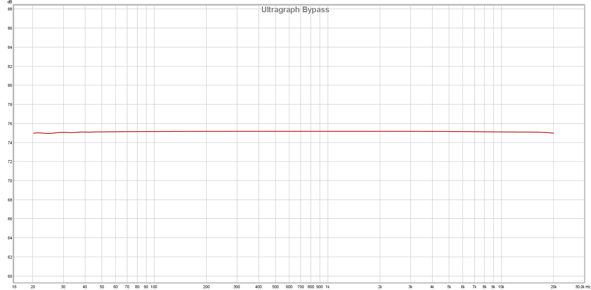
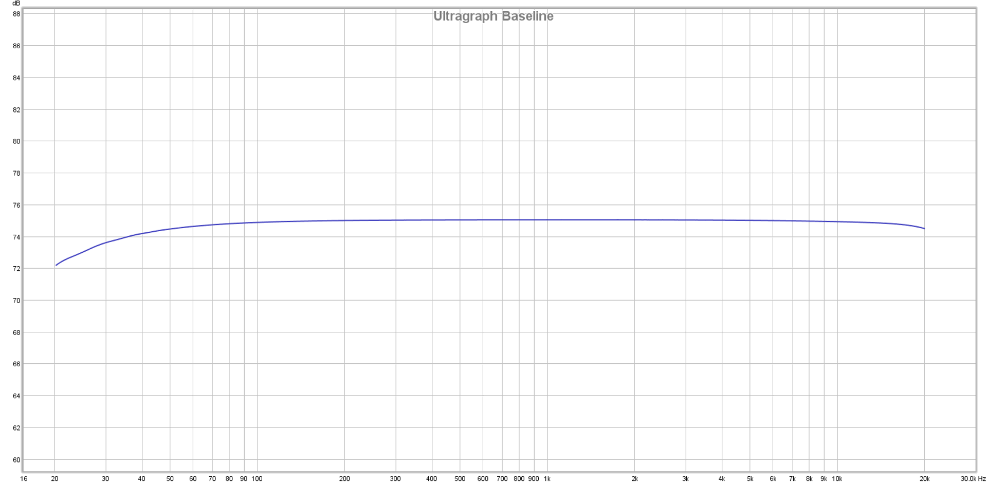
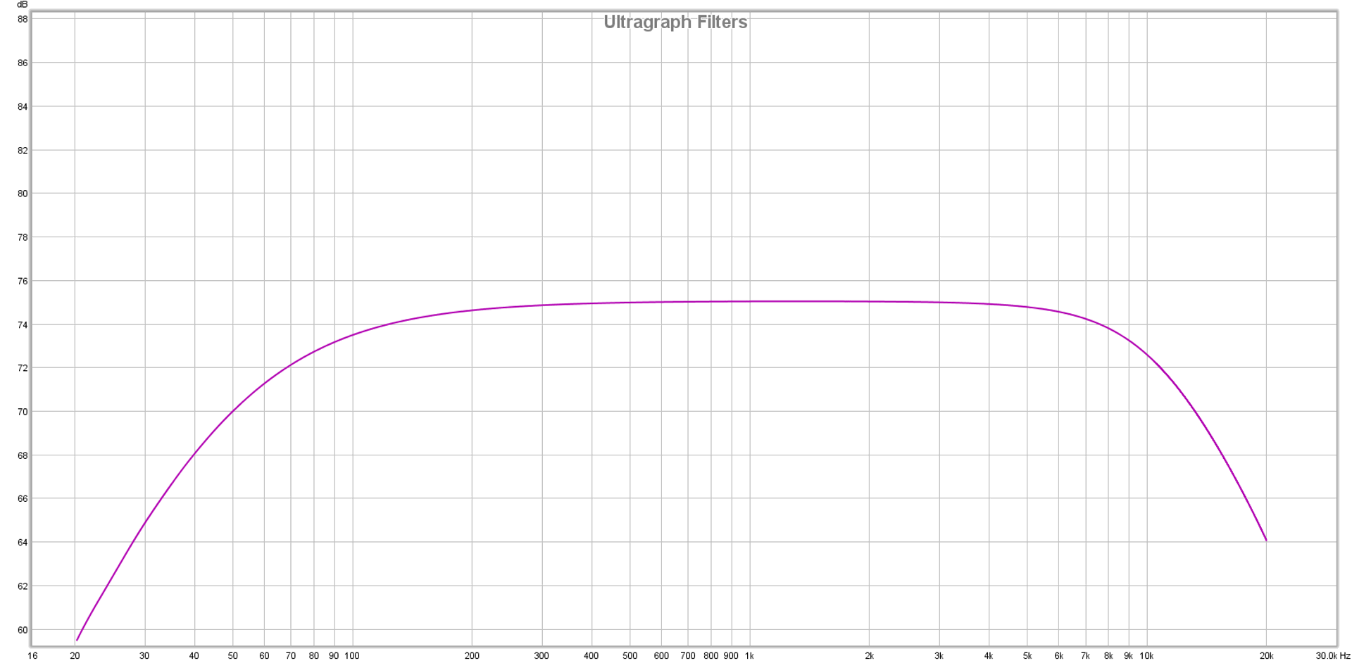
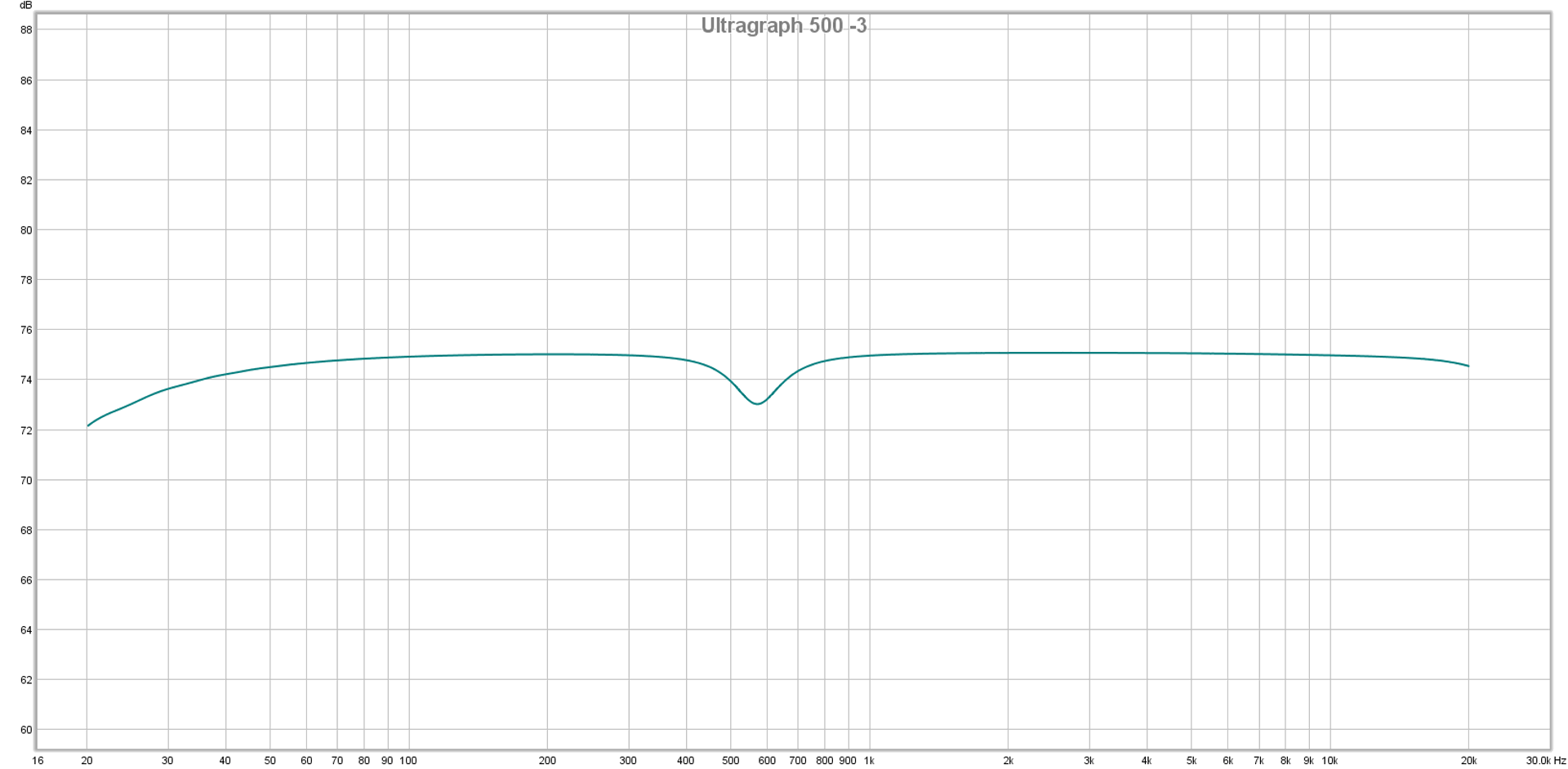
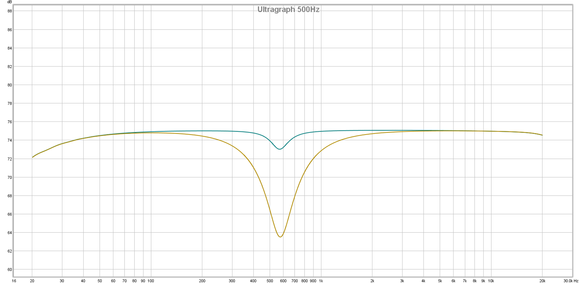
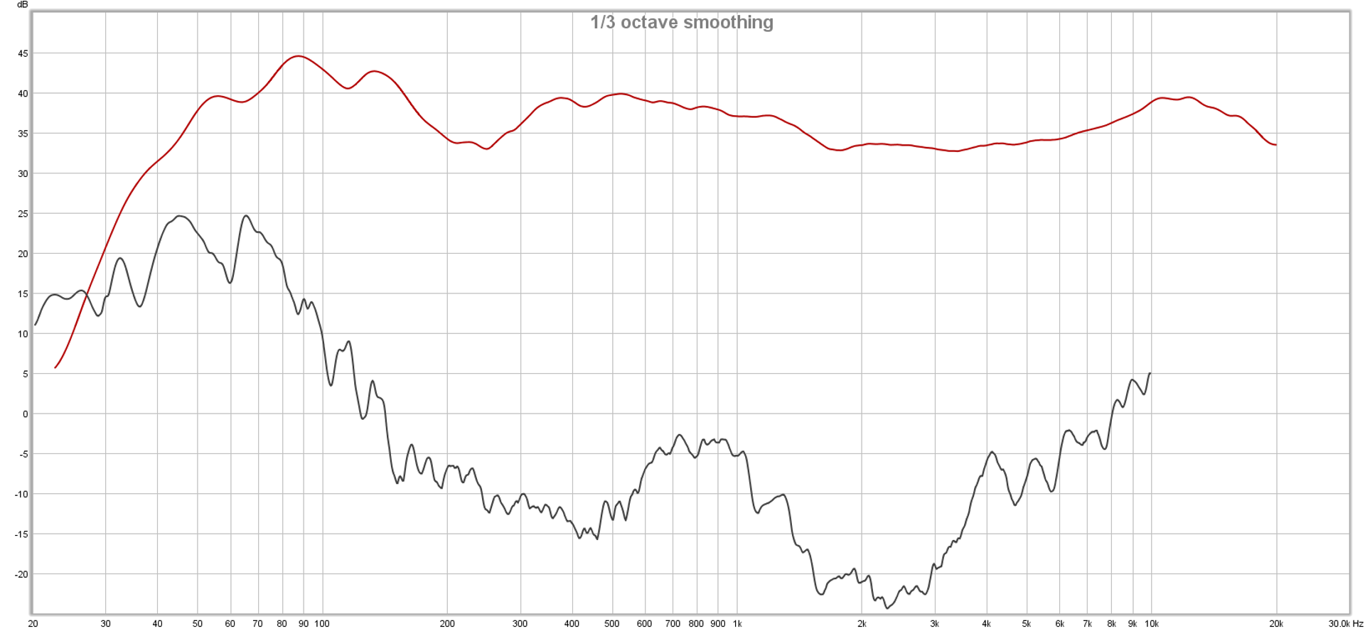
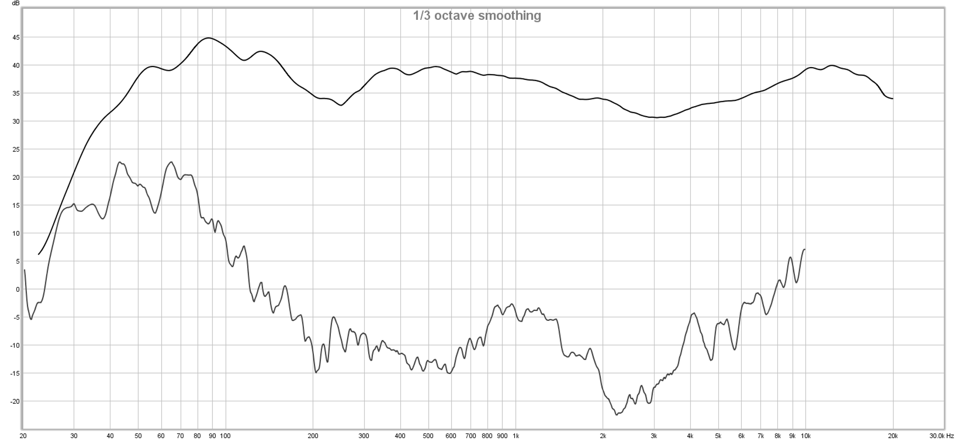
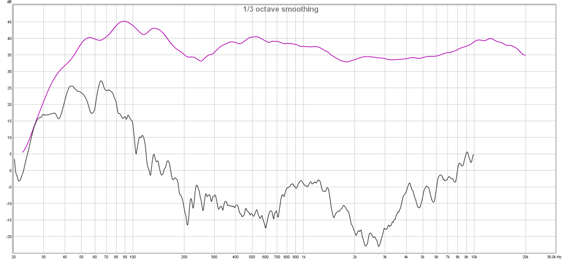
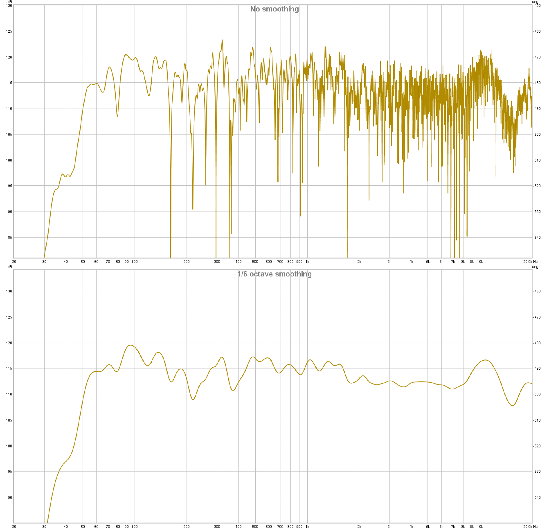
…until you realize that 0.22 ms is the 1/2 cycle time of 2272 Hz. With the outer boxes being 1/2 cycle late, 2272 Hz would null (as would other frequencies with the same phase relationship). If everything started as measuring perfectly flat, introducing that timing difference into a rig with multiple boxes producing the same material would result in this transfer function:

combfiltering0.22ms

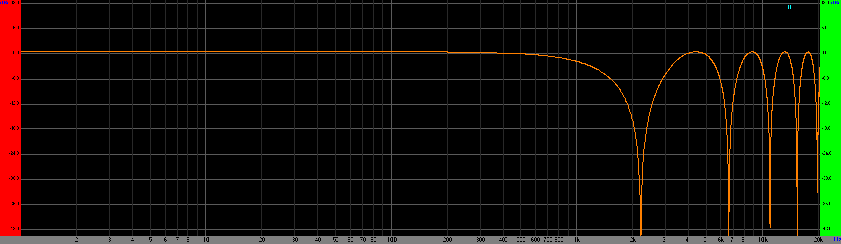
Of course, everything does NOT start out as being perfectly flat, so that craziness is added onto whatever other craziness is already occurring. For most of the audience, plenty of phase weirdness is going on from any PA deployed as two, spaced “stacks” anyway. To put it succinctly, running everything everywhere results in even more giant holes being dug into the critical-for-intelligibility range than were there before.

Running double hung, where the different pairs of boxes produce different sounds, prevents the above problem from happening.

So, when I said that I was running double hung for “clarity,” I was not doing it to fix an existing clarity problem. I was preventing a clarity problem from manifesting itself.

Running absolutely everything into every mid-high, and then having all those mid-highs combine is a simple way to make a system’s mid-highs louder. It’s also a recipe for all kinds of weird phase interactions. These interactions can be used intelligently (in an honest-to-goodness line-array, for instance), but for most of us, they actually make life more difficult. Louder is not necessarily better.

More On Output – Enough Rig For The Gig?

For some folks reading my previous installment, there was real concern that I hadn’t brought enough PA. They took a gander at the compactness of the rig, and said, “There’s no way that’s going to get big-time sound throughout that entire park.”

The people with that concern are entirely correct.

But “rock and roll level everywhere” was not at all what I was trying to do.

The Raw Numbers

What I’ve found is that many people do NOT actually want everything to be “rock and roll” loud over every square inch of an event area. What a good number of events actually want is a comfortable volume up close, with an ability to get away from the noise for the folks who aren’t 100% interested. With this being the case, investing in a system that can be clearly heard at a distance of one mile really isn’t worthwhile for me. (Like I said, I’m not trying to compete with a varsity-level sound company.)

Instead, what I do is to deploy a rig that’s in close proximity to the folks who do want to listen, while less interested people are at a distance. Because the folks who want more volume are closer to the PA, the PA doesn’t have to have crushing output overall. For me, the 110 dB SPL neighborhood is plenty loud, and I can do that for the folks nearby – by virtue of them being nearby.

Big systems that have to cover large areas often have the opposite situation to deal with: The distance differential between the front row and the back row can actually be smaller, although the front row is farther away from the stacks in an absolute sense. With my rig, the people up close are probably about three meters from the PA. The folks far away (who, again, aren’t really interested) might be 50 meters away. That’s more than a 16-fold difference. At a bigger show, there might be a barricade that’s 10 meters from the PA, with the main audience extending out to 100 meters. That’s a much bigger potential audience, but the difference in path lengths to the PA is only 10-fold.

Assuming that the apparent level of the show drops 6 dB for every doubling of distance, my small show loses about 24 decibels from the front row to the folks milling around at 50 meters. The big show, on the other hand, loses about 20 dB. (But they have to “start” much louder.)

That is, where the rubber hits the road is how much output each rig needs at 1 meter. At the big show, they might want to put 120 dB SPL into the front seats. To do that, the level at 1 meter has to be 140 dB. That takes a big, powerful PA. The folks in the back are getting 100 dB, assuming that delays aren’t coming into the picture.

For me to do a show that’s 110 dB for the front row, my PA has to produce about 119 dB at 1 meter. That’s right about what I would expect my compact setup to be able to do, with a small sliver of headroom. At 50 meters, my show has decayed to a still audible (but not “rock show loud”) 86 dB SPL.

That’s what I can do, and I’ve decided to be happy with it – because the folks I work with are likely to be just as happy with that as I am. People don’t hire me to cover stadiums or have chest-collapsing bass. They hire me because they know I’ll do everything in my power to get a balanced mix at “just enough” volume.

The Specifics Of The Show

Ultimately, the real brass tacks are to be found in what the show actually needed.

The show did not need 110 dB SPL anywhere. It needed a PA that sounded decent at a moderate volume.

The genre was folksy, indie material. A 110 dB level would have been thoroughly inappropriate overkill. At FOH control, the show was about 80 – 90 dB, and that was plenty. There were a few times where I was concerned that I might have been a touch too loud for what was going on. In that sense, I had far more than enough PA for raw output. I could have run a single pair of boxes and been just fine, but I didn’t want to get all the speakers out of the van and not use them. As I said before, I chose “double hung” to use all my boxes, and to use them in the way that would be nicest for people’s ears.


If you’re curious about running a double hung setup, I do encourage you to experiment with it. Curiosity is what keeps this industry moving. At the same time, you shouldn’t expect it to completely knock you off your feet. If you have a good-sounding system that runs everything through one pair of mains, adding another pair just to split out some sources is unlikely to cause a cloud-parting, ligh-ray-beaming experience of religious proportions. Somewhat like aux-fed subwoofers, going double hung is a taste-dependent route to accomplishing reinforcement for a live event. For me, it solves a particular problem that is mostly logistical in nature, and it sounds decent doing it.