Tag Archives: Signal Flow

The Order Matters

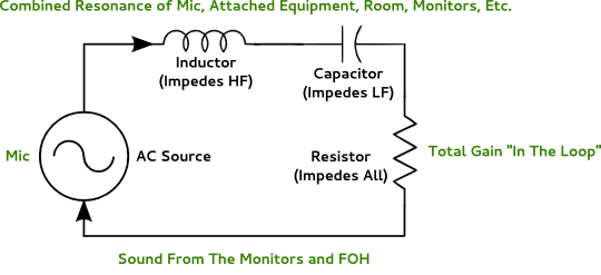
Getting your signal chain sorted out is key – especially when monitor world and FOH come together.

Please Remember:

The opinions expressed are mine only. These opinions do not necessarily reflect anybody else’s opinions. I do not own, operate, manage, or represent any band, venue, or company that I talk about, unless explicitly noted.

Sometimes, you have to do things that “break the rules.”

Audio-humans internalize a lot of pointers as they learn their craft, and those tactics are often in place for very good reasons. When a given way of making things happen has survived for decades, it’s usually because it’s either a really good idea, or we just haven’t found a way around it yet. The problem that arises, though, is that a lot of techs don’t know the “deep roots” of why certain signal flows are as they are.

For instance, just about everybody knows that a gate should – 99% of the time – be placed pre-compression. Not everybody can verbalize the “why” of that rule, though. The “deep root” of the rule is that dynamic range expansion (gating) works more effectively as the dynamic range of an input signal increases. The less of a level difference that you have between the material you want gated out and the material you want to keep, the less able you are to cause the gate to discriminate between the two. Compressing a signal at some point that’s pre-gate is just working against yourself, because compression is dynamic range reduction.

But I digress.

The point of this article isn’t to get into every kind of signal flow arrangement. The idea here is to relate an anecdote that shows why I had to “break some rules” recently. It was all in the name of getting FOH (Front Of House) and monitor world to play nicely.

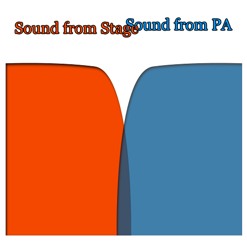
FX Out Front and On Deck

As I was soundchecking a band, one of the players expressed a request to have reverb on his instrument. He also specifically requested that the reverb be routed to the monitors.

Here’s where the trouble can start.

See, “everybody knows” that reverbs are fed from post-fader sends. Most of the time, this is the right thing to do. You use the send to create a reverb proportionality, and if you end up pushing the channel level around, the proportionality stays the same. If the fader goes up 6 dB, the reverb level goes up 6 dB – the wet/ dry mix remains as it was set. That’s a good thing.

Except when it isn’t.

The problem in the “Curious Case of a Reverb That’s Going to FOH and Monitor World” is that you DON’T want the reverb level to track with level changes out front. If it does, then the wet/ dry blend on deck can go all over the place during the show. This is especially true in small venues, where a instrument may be completely “out” until a solo, at which point you drive the level up into audible territory. That could mean an effective dynamic range of 80 db or more. Possibly a lot more.

Obviously, appearing and disappearing reverb isn’t what the gents on stage are after. As a result, the “post-fader sends to FX” rule has to go out the window, because it’s no longer appropriate. Instead, the reverb has to be run from a pre-fader send. As long as you don’t fiddle with your preamp gain, the reverb level will be unaffected by what you’re doing out front.

Or will it?

The other thing you have to be aware of is where that pre-fader send lives in relation to your channel EQ. If you have something bizarre going on with the channel EQ for FOH (and you very well might), and that pre-fader send takes a split AFTER the EQ, your reverb may sound awfully strange.

What To Do, What To Do?

The first thing that you have to do is prioritize. In most cases, making a consistent blend “easy” for monitor world should come before making FOH easy. (There’s probably a whole article to be written about this, but the short version is that you can often hear, and act on, issues in FOH faster than issues on deck.)

The next thing to do is to figure out what you need for that prioritization to be fulfilled. In this case, I needed reverb that was driven from a pre-fader, pre-EQ signal. I also needed the “wet” audio from the reverb to be independently routable to FOH and the monitor wedges. Making this happen for me is no problem, because I run a console with insanely flexible routing. I can actually use “subchannels” within channels to pass audio “around” processors, and any channel can send to or receive from any other channel. I also have the built-in option to run sends pre or post any channel processing.

But, what if you don’t have all that?

Heck, what if you don’t have completely separate sets of channels for FOH and monitor land?

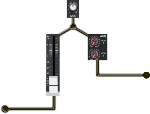
You can still make this happen. Take a look:

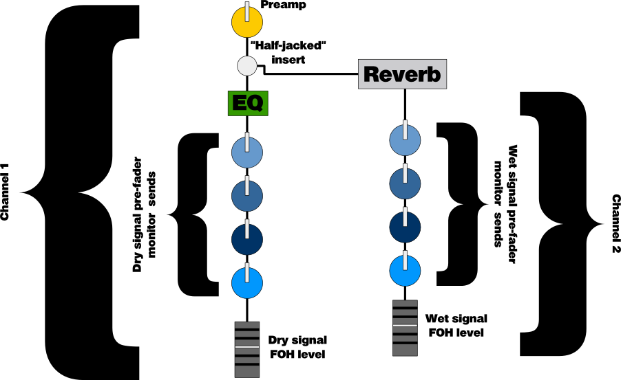
The “half-jacked” insert lets you mult (split) the original signal over to the reverb. At the same time, the signal continues to flow through the FOH channel and its monitor sends. You can then take the reverb processor’s output, put that in a different channel, and use the pre-fader sends to get reverb to monitor world. The reverb channel’s fader output can then be blended into FOH as necessary.

With this kind of setup, you can go hog-wild with your FOH levels, and monitor world won’t be directly affected. There are other ways of accomplishing this, of course, but this setup is one of the simpler ones.

Yes, this is a bit more complicated than what you might think of “off the cuff,” but it lets you have what you need out front without compromising what the folks on deck can have for themselves. I think it’s worth doing if you have the channels, and it’s not that hard to adapt to your own needs…

…you just have to remember that “the order matters.”


Rusted Moose Live Broadcast

Check out live music from Utah at AMR.fm.

Please Remember:

The opinions expressed are mine only. These opinions do not necessarily reflect anybody else’s opinions. I do not own, operate, manage, or represent any band, venue, or company that I talk about, unless explicitly noted.

When you leave a large land-based mammal out in the rain, you might just end up with a Rusted Moose. The stream is scheduled to begin at 7:00 PM, Utah local time (MST). The stream will be accessible through AMR.fm.

…and yes, we are definitely aware of the issues that cropped up with last week’s show. A live broadcast of a show that’s also live (to an actual audience in the room) is a thing with many moving parts, and we failed to nail down one of those moving parts. Specifically, we never positively determined what the broadcast feed was “listening” to – and wouldn’t you know, the feed was listening to the laptop’s built-in microphone.

Yowza.

I should write an article about all this sometime. 🙂


The Acoustic Crossover

If you don’t need it, don’t spend power (or volume) on it.

Please Remember:

The opinions expressed are mine only. These opinions do not necessarily reflect anybody else’s opinions. I do not own, operate, manage, or represent any band, venue, or company that I talk about, unless explicitly noted.

For loudspeakers, a crossover is used to separate full-range audio into multiple “passbands,” with each passband being appropriate for a certain enclosure or driver. For instance, there’s no need to send a whole bunch of high-frequency information to a large-diameter speaker if you’ve also got a handy device that’s better for top-end. On the flipside, failing to filter low-frequency information is a good way to wreck a “meant for HF” output transducer.

A beautifully implemented crossover creates a smooth transition from box to box and driver to driver. Crossovers can also help with getting the maximum performance out of an amplifier/ loudspeaker chain – again, because pushing material to a driver that can’t reproduce it is a waste of power.

Most of the time, we think of a crossover as an electrical device. Whether the filter network is a bunch of passive components at the end of a speaker cable, or a DSP sitting in front of the amplifiers, the mental image of a crossover is that of a signal processor.

…but remember how I’ve talked about acoustical resonant circuits? The reality of the pro-audio life, especially in small rooms, is that the behaviors of electrical devices show up in acoustical form all the time. In the past few years, I’ve found that creating acoustical crossovers between the stage wash and the FOH (Front of House) PA can be incredibly useful.

Why This Matters In Small Rooms

In a small venue, you don’t always have a lot of power to spare. It’s rarely practical to deploy a PA system that can operate at “nothing more than a brisk walk” for most of the show. Instead, you’re probably using a LOT of the audio rig’s capability at any given time.

Even if you have a good deal of power to spare, you often don’t have very much volume to spare. A small venue gets loud in a big hurry – not only because of acoustics, but because the average audience member is “pretty dang close” to the stage and PA.

Taken together, these issues present hat-explodingly good reasons to avoid chewing up your power and/ or SPL budget with audio that you just don’t need. Traditionally, dealing with this has taken the form of not reinforcing entire sources or channels. (This can oftentimes, and unfortunately, be appropriate. I’ve done several shows where one person was so loud that everyone EXCEPT them was in the PA.) An “all-or-nothing per channel” approach is sometimes a bit too much, though. What can be better is to use powerful and dramatic, yet judiciously applied subtractive EQ.

Aggressive Filtration

A good way to illustrate what I mean by “powerful and dramatic, yet judiciously applied subtractive EQ” is to show you some analysis traces. For instance, here’s my starting point for a vocal HPF (High Pass Filter):

vocalfilter

The filter frequency is 500 Hz. Effectively, I’m chucking out everything at or below about 250 Hz.

“But, doesn’t that sound really thin,” you ask?

Indeed, it does sound a bit thin at times. If I don’t have a lot of monitor wash, or the singer doesn’t have a voice that’s rich in low-mid, or if they just don’t want to get right up on the mic, then I need to roll my filter down. On the other hand, in situations where the monitors were loud, the vocalists had strong voices, and they had their lips stuck to the mics, I’ve had HPF filters up as high as 1 kHz or more.

The point is that the stage-wash often gives me everything I need for low-mid in the vocals, so why duplicate that energy in the FOH PA? If I create a nice transition between the PA and what’s already in the room, I only have to spend power on what I need for clarity.

Now, here’s a trace for a guitar amp:

guitarfilter

Of course, you don’t necessarily need something as extreme as this all the time. What’s great about filtering a guitar like this, though, is that you’ve thrown away everything except the “soul” of the instrument – 400 Hz to 2 kHz. Especially with “overly scooped” guitar sounds, what you need for the guitar to actually sit in the live mix is more midrange than what you’re getting. Of course, you could turn up the ENTIRE guitar to get what you need – but why? You’ll be killing the audience. It’s much better to “just turn up the mids” without turning up anything else.

…and even if the guitar is only really in the PA during solos, this kind of filter can still be a good thing to implement. If you have to REALLY get on the gas for a lead part, you can avoid tearing people’s heads off with piercing high end – as well as avoid stomping all over the rhythm player and the bassist.

By combining a highly filtered sound with the stage volume, you effectively get to EQ the guitar without having to completely overwhelm the natural sound from the amp. (This is just an acoustical version of what multiband equalizers do anyway. You select a frequency range to work on, and everything else is left alone. Whether this happens purely with electrical signals or in combination with acoustic events is relevant, but ultimately a secondary issue.)

Now, how about a kick drum?

kickfilter

Again, this kind of thing isn’t appropriate in all contexts. You wouldn’t do this for a jazz gig…but in a LOT of other situations, what you need from the kick drum is “thump” and an appropriately placed “pop” or “click.”

And that’s it.

In a small venue, reproducing much of a rock or pop kick’s midrange is unhelpful. All you do is run over everything else, which makes you turn up everything else, which makes your whole mix REALLY LOUD.

Instead, you can create an acoustical crossover to sweeten the kick “just enough,” without getting any louder than necessary.

All Wet

Saving power and volume also applies for situations where you want effects to come from the PA. It’s very easy to get too loud when you want to put reverb, delay, or even chorus on something. The reason for this is because these effects have a “dry” (unprocessed) component, that has to be blended properly with the “wet” sound. What can happen, then, is that you end up pushing the entire sound up too far – because you want to hear the effects. The “dry” sound in the signal combines with the “dry” sound in the room, which makes for an acoustical result that isn’t as “wet” as you wanted…so, you push the volume until the “dry” sound through the PA overwhelms the sound in the room.

That can be pretty loud.

Instead of brute force, though, you can just tilt the “wet” ratio much further in favor of the effect.

In fact, I’ve been in some situations where, say, a snare drum was in exactly the right place without any help from the PA. In that case, I set up my routing so that the snare reverb was 100% wet – no “dry” signal at all. I already had all the “dry” sound I needed from the snare in the room, and so I just turned up the “all wet” reverb until the total, acoustical result was what I wanted.

The bottom line with all this is that, in a small space, you can get pretty darn decent sound without a screaming-loud PA. You just have to use the sound that you already have, and very selectively add the bits that need a little help. The more fine-grained you can be with the creation of this acoustic crossover, the more you can bend the total acoustical result to your will…within reason, of course.


Offline Measurement

Accessible recording gear means you don’t have to measure “live” if you don’t want to.

Please Remember:

The opinions expressed are mine only. These opinions do not necessarily reflect anybody else’s opinions. I do not own, operate, manage, or represent any band, venue, or company that I talk about, unless explicitly noted.

I’m not an audio ninja. If you make a subtle change to a system EQ while the system is having pink noise run through it, I may or may not be able to tell that you’ve made a change, or I may not be able to tell you how wide or deep a filter you used. At the same time, I highly recognize the value of pink noise as an input to analysis systems.

“Wait! WAIT!,” I can hear you shouting, “What the heck are you talking about?”

I’m talking about measuring things. Objectivity. Using tools to figure out – to whatever extent is possible – exactly what is going on with an audio system. Audio humans use function and noise generators for measurement because of their predictability. For instance, unlike a recording of a song, I know that pink noise has equal power per octave and all audible frequencies present at any given moment. (White noise has equal power PER FREQUENCY, which means that each octave has twice as much power as the previous octave.)

If that paragraph sounded a little foreign to you, then don’t panic. Audio analysis is a GINORMOUS topic, with lots of pitfalls and blind corners. At the same time, I have a special place in my heart for objective measurement of audio devices. I get the “warm-n-fuzzies” for measurement traces because they are, in my mind, a tool for directly opposing a lot of the false mythology and bogus claims encountered in the business of sound.

Anyway.

Measurement is a great tool for dialing in live-sound rigs of all sorts. Because of its objectivity (assuming you actually use your measurement system correctly), it helps to calibrate your ears. You can look at a trace, listen to what something generating that trace sounds like, and have a reference point to work from. If you have a tendency to carve giant holes in a PA system’s frequency response when tuning by ear, measurement can help tame your overzealousness. If you’re not quite sure where that annoying, harsh, grating, high-mid peak is, measurement can help you find it and fix it.

…and one of the coolest things that I’ve discovered in recent years is that you don’t necessarily have to measure a system “live.” Offline measurement and tuning is much more possible than it ever has been before – mostly because digital tech has made recording so accessible.

How It Used To Be And Often Still Is

Back in the day, it was relatively expensive (as well as rather space-intensive and weight-intensive) to bring recording capabilities along with a PA system. Compact recording devices had limited capabilities, especially in terms of editing. Splicing tape while wrangling a PA wasn’t something that was going to happen.

As a result, if you wanted to tune a PA with the help of some kind of analyzer, you had to actually run a signal through the PA, into a measurement mic, and into the analysis device.

The sound you were measuring had to be audible. Very audible, actually, because test signals have to drown out the ambient noise in the room to be really usable. Sounds other than the test signal being audible to the measurement mic mean that your measurement’s accuracy is corrupted.

So, if you were using noise, the upshot was that you and everybody else in the room had to listen to a rather unpleasant blast of sound for as long as it took to get a reference tuning in place. It’s not much fun (unless you’re the person doing the work), and you can’t do it everywhere. Even when using a system that can take inputs other than noise, you still had to measure and make your adjustments “live,” with an audible signal in the room.

Taking A Different Route

The beautiful thing about today’s technology is that we have alternatives. In some cases, you might prefer to do a “fully live” tuning of a PA system or monitor rig – but if you’d prefer a different approach, it’s entirely possible.

It’s all because of how easy recording is, really.

The thing is, any audio-analysis system doesn’t really care where its input comes from. An analyzer really isn’t bothered about if its information is coming from a live measurement mic, or if the information is a recording of what came out of that measurement mic. All the analyzer knows is that some signal is being presented to it.

If you’re working with a single-input analyzer, offline measurement and tuning is basically about getting the “housekeeping” right:

  1. Run your measurement signal to the analyzer, without any intervening EQ or other processing. If that signal is supposed to give you a “flat” measurement trace, then make sure it does. You need a reference point that you can trust.
  2. Now, disconnect the signal from the analyzer and route that same measurement signal through the audio device(s) that you want to test. This includes the measurement mic if you’re working on something that produces acoustical output – like monitor wedges or an FOH (Front Of House) PA. The actual thing that delivers the signal to be captured and analyzed is the “device-under-test.” For the rest of this article, I’m effectively assuming that the device-under-test is a measurement mic.
  3. Connect the output of the device-under-test to something that can record the signal.
  4. Record at least several seconds of your test signal passing through what you want to analyze. I recommend getting at least 30 seconds of recorded audio. Remember that the measurement-signal to ambient-noise ratio needs to be pretty high – ideally, you shouldn’t be able to hear ambient noise when your test signal is running.
  5. If at all possible, find a way to loop the playback of your measurement recording. This will let you work without having to restart the playback all the time.
  6. Run the measurement recording through the signal chain that you will use to process the audio in a live setting.
  7. Send the output of that signal chain to the analyzer, but do NOT actually send the output to the PA or monitor rig.

Because the recorded measurement isn’t being sent to the “acoustical endpoints” (the loudspeakers) of your FOH PA or monitor rig, you don’t have to listen to loud noise while you adjust. As you make changes to, say, your system EQ, you’ll see the analyzer react. Get a curve that you’re comfortable with, and then you can reconnect your amps and speakers for a reality check. (Getting a reality check of what you just did in silence is VERY important – doubly so if you made drastic changes somewhere.)

Dual-FFT

So, all of that up there is fine and good, but…what if you’re not working with a simple, single input analyzer? What if you’re using a dual-FFT system like SMAART, EASERA, or Visual Analyzer?

Well, you can still do offline measurement, but things get a touch more complicated.

A dual-FFT (or “transfer function”) analysis system works by comparing a reference signal to a measurement signal. For offline measurement to work with comparative analysis, you have to be able to play back a copy of the EXACT signal that you’ll be using for measurement. You also have to be able to play that signal in sync with your measurement recording, but on a separate channel.

For me, the easiest way to accomplish this is to have a pre-recorded (as opposed to “live generated”) test signal. I set things up so that I can record the device-under-test while playing back the test signal through that device. For example, I could have the pre-recorded test signal on channel one, connect my measurement device so that it’s set to record on channel two, hit “record,” and be off to the races.

There is an additional wrinkle, though – time-alignment. Dual-FFT analyzers give skewed results if the measurement signal is early or late when compared to the reference signal, because, as far as the analyzer is concerned, the measurement signal is diverging from the reference. Of course, any measured signal is going to diverge from the reference, but you don’t want unnecessary divergence to corrupt the analysis. The problem, though, is that your test signal takes time to travel from the loudspeaker to the measurement microphone. The measurement recording, when compared to the reference recording, is inherently “late” because of this propagation delay.

Systems like SMAART and EASERA have a way of doing automatic delay compensation in a quick and painless way, but Visual Analyzer doesn’t. If your software doesn’t have an internal method for delay compensation, you’ll need to do it manually. This means:

  1. Preparing a test signal that includes an audible click, pop, or other transient that tells you where the signal starts.
  2. After recording the measurement signal, you’ll need to use that click or pop to line up the measurement recording with the test-signal, in terms of time. The more accurate the “sync,” the more stable your measurement trace will be.

If you’d rather not make your own test signal, you’re welcome to download and use this one. The “click” at the beginning is several cycles of a 2 kHz tone.

The bottom line is that you can certainly do “live” measurements if you want to, but you also have the option of capturing your measurement for “silent” tweaking. It’s ultimately about doing what’s best for your particular application…and remembering to do that “reality check” listen of your modifications, of course.


Fixing The Wrong Thing

Cleverness is only helpful if it’s applied to the right problem.

Please Remember:

The opinions expressed are mine only. These opinions do not necessarily reflect anybody else’s opinions. I do not own, operate, manage, or represent any band, venue, or company that I talk about, unless explicitly noted.

Back in October, I ran a fog machine “dry” by fixing it’s remote switch. Not directly, you understand. In an effective sense.

Here’s the story:

I switched over to an actual, honest-to-goodness continuous hazer after my old unit refused to unclog. I still had juice for the old hazer, though, and I didn’t want to just toss it out. I discovered that we had an old fogger that still worked, and the leftover haze juice was water based – thus, it would be (mostly) compatible with the fogger. I decided to take the new hazer out of service for long enough to burn off the old haze fluid.

I rigged up an extension to the fogger’s remote so that I could drive the output from FOH (Front Of House). In the process of making my extension work, I discovered that something was amiss in the remote’s switch wiring. I did some light pulling and finagling, and a proper connection was re-established.

Groovy. (Yes, that’s a shout out to “Army of Darkness,” even though you couldn’t tell.)

The fogger went back into service in time for a two-band show. The opener ended up pushing their downbeat time back about 30 – 45 minutes, but I wanted to establish some atmosphere (literally and figuratively) while we waited.

So, I hit the “Fog” button, and nothing happened. I figured that the button wiring had gotten tweaked again, so I pushed and pulled on the remote’s strain relief…hey, look! Fog! Nice.

The fog unit vented its output into a fan, and I got a pretty-okay haze effect out of the whole shebang. The hang-time on the haze wasn’t very long, though, so the stage ended up clearing in only a few minutes.

I kept hitting the button.

We got through most of the first act’s set, when I suddenly didn’t get fog anymore.

“Freakin’ button.” I thought. “I’m going to just open up the unit and twist the conductors together. It won’t be as nice as having the button, but I can still yank the extension connection if the haze gets out of control.”

And that’s exactly what I did. As the first band was getting their gear off the deck, I was unscrewing the cover on the remote and shorting the wires that would otherwise be connected to different poles on the “Fog” switch. Satisfied that I had performed a nifty little bit of “rock and roll” surgery, I got set for the main act.

The band’s first set got rolling, and I connected my remote.

No fog.

“The connection at the machine end must be bad. Oh well, I’ll fix that later.”

When I finally got up on deck and took a look at the fog machine, I realized what the problem actually was: In the process of keeping the venue hazy during walk-in and the opener, I had run the (rather small) fog tank completely dry. The remote wasn’t the problem at all.

Seriously, if the fogger had been a car, I would have just tried to fix the issue of not having any gas by tearing down and rebuilding the steering column. Whoops.

If Fixing A Problem Doesn’t Fix THE Problem, You’ve Fixed The Wrong Problem

I had just been bitten by what some folks call “The Rusty Halo Effect.” A rusty halo is a sort of mental designation that we humans give to things that have caused us trouble in the past. If a person, piece of gear, venue, component, or really anything has been a point of failure before, we tend to assume that the same thing will be the point of failure again. This can actually be quite helpful, because we can build and maintain an internal list of “bits to check if you’re having problems.” Being good with the list can make you look like a fix-it ninja…

…but assuming that your list is complete can cause you to miss different causes for similar problems.

I’ll go so far as to say that most of my really embarrassing audio problems in the last few years have been due to “Fixing The Wrong Thing,” or “Misdiagnosing The Problem.” Not so long ago, I was soundchecking a drummer who wanted a lot of the kit in the drumfill. We were getting everything dialed up, and I had taken a stab at getting some levels set on the sends from the drum mics. We started to really work on the kick sound, and when we got it to the right point we also found the point where feedback became a problem.

“I’ll just notch that out,” I thought. I got into the kick mic EQ for monitor world, and starting sweeping a narrow-ish filter around the area of the big, low-frequency ring we were dealing with. Strangely, I couldn’t find the point where the filter killed the feedback.

I muted the kick mic. The feedback slowly died. Much more slowly than I would normally have expected.

This is what tipped me off to me having tried to fix the wrong problem. If a single channel is, overwhelmingly, the culprit in a feedback situation, then muting that channel should kill the feedback almost instantaneously. If that’s not the case, then you’ve muted the wrong channel.

The real problem was one of the tom mics. It was perfectly stable as long as no low-frequency acoustic energy was present, but when the drummer hit the kick there was a LOT of LF energy introduced into the tom mic, the actual tom itself, and the drumfill. All that together created an acoustical circuit that rang, and rang, and rang…right up until I muted the offending tom mic.

Silence.

I killed the appropriate frequency in the tom mic, and we were all happy campers.

So – what can be generalized from these two stories? Well:

For troubleshooting, try to maintain a skillset that includes rapid isolation of problem areas. If a suspected problem area is isolated and removed from the involved system, and the problem persists, then the problem area is actually elsewhere.

Corollary: It is very important that you strive to know EXACTLY how the individual parts of your system connect and communicate with each other.

In other words: Try not to fix the wrong thing.


Mixing A Live Album: Drums

In a rock mix, you may find yourself “really turnin’ the knobs” when it comes to the drums.

Please Remember:

The opinions expressed are mine only. These opinions do not necessarily reflect anybody else’s opinions. I do not own, operate, manage, or represent any band, venue, or company that I talk about, unless explicitly noted.


Mixing A Live Album: Guitar

Sometimes, making something sound big means reducing dynamic range and narrowing the overall frequency response.

Please Remember:

The opinions expressed are mine only. These opinions do not necessarily reflect anybody else’s opinions. I do not own, operate, manage, or represent any band, venue, or company that I talk about, unless explicitly noted.


Split Monitor For The Little Guy

You don’t have to be in the big-leagues of production to get big-league functionality.

Please Remember:

The opinions expressed are mine only. These opinions do not necessarily reflect anybody else’s opinions. I do not own, operate, manage, or represent any band, venue, or company that I talk about, unless explicitly noted.

So, I’ve already talked a bit about why “split monitoring” is a nifty idea. Independent signal paths for FOH and monitor world let you give the folks onstage what they want, while also giving FOH what you want – and without having to directly force either area’s decisions on the other.

…but, how to set this up?

Traditional split-monitor setups are usually accomplished with a (relatively) expensive onstage split. Individual mic lines are connected to the stagebox, which then “mults” the signal into at least two cable trunks. This can be as simple as bog-standard parallel wiring – like you can find in any “Y” cable – or it can be a more complex affair with isolation transformers.

While you can definitely use a splitter snake or stagebox to accomplish the separation of FOH from monitor world, the expense, weight, and hassle may not really be worth it. Traditional splitters are usually built with the assumption that there will be separate operators for FOH and monitor world, and that these operators will also be physically separated. As a result, the cable trunks tend to be different lengths. Also, those same cables are made of a lot of expensive copper and jacketing material, and the stagebox internals can be even more spendy.

Now, if you actually need the functionality of a full-blown splitter snake, you should definitely invest in one. However, if you just want to get in on the advantages of a split monitor configuration, what you really need to shift your spending to console functionality and connectivity.

General Principles

Whether you implement a split monitor solution via analog or digital means, there are some universally applicable particulars to keep in mind:

  • You need to have enough channels to handle all of your inputs twice, OR you need enough channels to handle the signals that are “critical for monitoring” twice. For instance, if you never put drums in the monitors, then being able to “double up” the drum channels isn’t necessary. On the other hand, only doubling certain channels can be more confusing, especially for mixes with lots of inputs.
  • You actually DON’T need to worry about having enough pre-fader aux sends. In a split monitor configuration, post-fader monitor sends can actually be very helpful. Because you don’t have to worry about FOH fader moves changing the monitor mixes, you can run all your monitor sends post fader. This lets you use the monitor-channel fader itself as a precise global trim.
  • If the performers need FX in the monitors, you need to have a way to return the FX to both the FOH and monitor signal paths.
  • You need to be wiling to take the necessary time to get comfortable with running a split monitor setup. If you’ve never done it before, it can be easy to get lost; try your first run on a very simple gig, or even a rehearsal.

With all of that managed, you can think about specific implementations.

Analog

To create an affordable split monitor rig with an analog console (or multiple consoles), you will need to have a way to split the output of one mic pre to both the FOH and monitor channels. You can do this by “Y” cabling the output of external pres, but external mic preamps tend to be pretty spendy. A much less expensive choice is to use the internal pres on insert-equipped consoles. Ideally, one pre should be the “driver” for each source, and the other pre should be bypassed. Whether you pick the FOH or monitor channel pre is purely a matter of choice.

Your actual mic lines will need to be connected to the “driver” pre. On most insert-equipped consoles, you can plug a TS cable into the insert jack halfway. This causes the preamp signal to appear on the cable tip, while also allowing the signal to continue flowing down the original channel. The free end of the TS cable should also be connected to the insert on the counterpart channel, but it will need to be fully inside the jack. This connects the split signal to the electronics that are downstream of the preamp.

If you are working on a single console, you will need to be extra careful with your routing. You’ll need to take care not to drive your monitor sends from FOH channels, and on the flipside, you should usually disconnect your monitor channel faders from all outputs. (If all your monitor auxes are set as pre-fader, you can connect your monitor channel faders to a subgroup to get one more mix. This costs you your “global trim” fader functionality, of course. Decisions, decisions…)

Digital

Some digital consoles can allow you to create a “virtual” monitor mixer without any extra cables at all. If the digital patchbay functions let you assign one input to multiple channels, then all you have to worry about is the post-split routing. Not all digi consoles will let you do this, however. There are some digital mixers on the market that are meant to bring certain aspects of digital functionality to an essentially analog workflow, and these units will not allow you to do “strange” patching at the digital level.

As with the analog setup, if you’re using a single console you have to be careful to avoid using the monitor auxiliaries on the FOH channels. You also have to disconnect the monitor faders from all post-fade buses and subgroups – usually. Once again, if you don’t mind losing the fader-as-trim ability, setting all your monitor auxes to pre-fader and connecting the fader to a subgroup can give you one more mix.

Split-monitor setups can be powerful tools for audio rigs with a single operator. The configuration releases you from the compromises that can’t be avoided when you drive FOH and monitor land from a single channel. I definitely recommend trying split monitors if you’re excited about sound as its own discipline, and want to take your system’s functionality to the next level. Just take your time, and get used to the added complexity gradually.


Why A “Split Monitor” Configuration Is Cool

Running separate channels for FOH and monitor world can be a big help.

Please Remember:

The opinions expressed are mine only. These opinions do not necessarily reflect anybody else’s opinions. I do not own, operate, manage, or represent any band, venue, or company that I talk about, unless explicitly noted.


Impedance Is Life

The concept of impedance is everywhere in audio – even outside the electrical circuits involved.

Please Remember:

The opinions expressed are mine only. These opinions do not necessarily reflect anybody else’s opinions. I do not own, operate, manage, or represent any band, venue, or company that I talk about, unless explicitly noted.

One of the best things about working in live-audio is that, every so often, you have a mind-blowing experience.

Sometimes, it’s a band that plays the perfect gig.

Sometimes, it’s a piece of gear that rearranges your workflow in a supremely nifty way.

Sometimes, it’s discovering something about the fundamentals of the craft – an experience where you see a “primal pattern” emerge.

Just recently, I had that experience with impedance. (Also with tuned circuits, but that was by extension.) As a formally trained audio tech, I’ve been through the requisite material about what impedance is, and why it’s important – especially for power amplifiers and loudspeakers. What I failed to see – for FREAKIN’ years – is how impedance is a primal pattern in the entire experience of live audio. That is to say, the concept of impedance (and its effect on the performance of a “loop”) has universal applicability in terms of modeling and describing the behavior of live-sound gear in “real life.”

The spark for recognizing this came from my recent post on active DI boxes. A few days afterward, something suddenly clicked in a way that it hadn’t before.

Basically, impedance is everywhere. Here are a few examples.

Acoustical Impedance Bridging

Electrical voltage is analogous to the force behind the movement of a fluid or gas. This is why there are so many electrical engineering examples that use a garden hose as a metaphor. If you increase the impedance of the hose output, the system pressure goes up, flow goes down, and you can squirt a jet of water over to that tree in the center of the lawn. By putting your finger over the hose end, you create a bridging impedance between the hose and the outside environment.

This is why we have horn-loaded loudspeakers. Although greater amplifier output has allowed us to use more direct-radiating cone drivers, pro-audio still overwhelmingly uses high-frequency transducers that are mated to horns. One major reason for this is for purposes of controlling directivity. However, I would personally argue that the main reason for using a horn is for managing acoustical impedance.

When compared to a big, heavy, LF component like a woofer, a high-frequency driver has a rather high acoustical output impedance. It just can’t move enough air to create the kind of total, in-room pressures that a big driver can manage. An HF driver without a horn is like a tiny, low-pressure pipe that empties into a giant storm-drain. Sure, there’s no opposition to the flow of air pressure, but that tiny pipe can’t fill what it’s emptying into. Fire a high-frequency transducer freely into the air of a comparatively huge room, and it’s just not as effective as it might be. The room has too low of an input impedance – you need to bridge it.

That’s what the horn is for.

Mate the HF driver to a proper horn, and what you get is a situation where the horn partially opposes the pressure flow from the driver. The acoustical impedance that the HF driver “sees” is effectively raised, which means we get much better pressure transfer to the room – just like electrical impedance bridging gives us better voltage transfer between devices. “Loudness” is SPL, or Sound Pressure Level. We do need an adequate amount of “flow,” but our main concern is pressure transfer to the room.

In this way, the horn is like our finger over the end of the hose. Our flow of sound is restricted to a smaller radiation area (directivity), but within our radiation area we get a lot more pressure (loudness). We trade the ability to hit the entire room with a little bit of HF pressure for the ability to hit a small portion of the room with much more pressure.

Damped Motion

Another place where impedance is very important is with any resonant system. Resonant systems are damped by impedance; higher impedances prevent the system from “ringing” freely.

Resonance damping is an important factor when working with drivers mated to ported boxes. As the driver moves, the air mass inside the box partially impedes the motion of the driver. The pressurized air resists the driver’s inward travel. Add a port to the box, and you essentially add an acoustical inductor to the equation. At high frequencies, the driver continues to see a high impedance to inward motion. However, frequencies lower than the port’s resonance present very little acoustical impedance. Low impedance means a lack of damping, and this is can be a very…expensive thing. An undamped loudspeaker can have so much physical motion that it goes right past its design limits and tears itself apart.

So, when you buy a ported loudspeaker from a manufacturer, it’s important to heed the warnings about applying a high-pass filter at a certain frequency. Driving the system with material that’s lower than what the system is designed for can wreck the driver(s) in a hurry – all because the acoustical impedance is too low.

Feedback

The material above is information that I had some familiarity with. I hadn’t really bothered to dig into the impedance aspect of it all, but I was familiar with the terminology and that impedance was somehow involved.

Here’s where the lightbulb really came on, though.

What happened was that I applied an analogy to a live-sound reinforcement system that I never had before: I suddenly realized that a live-sound rig can be modeled as a giant LCR circuit.

An LCR circuit is an electrical device where current flows through an inductor, a capacitor, and a load. The inductor impedes high-frequency signals, while the capacitor impedes low frequency signals. This being the case, the circuit resonates or “rings” across a certain frequency range. This ringing is damped by the impedance of the load.

Resonance.

Ringing.

Like feedback.

Whoa.

This is where it hit me.

A live audio system is a (partially) closed loop. The sound from a microphone is amplified through loudspeakers, and some of that sound returns to the microphone and is amplified through the loop again. If the system gain is increased, that amplification increases. With enough amplification the most resonant frequency areas will begin to “ring” out of control. Feedback. Reduce the gain, and the feedback stops. That means that the system gain is the “load,” and that raising the gain means…

…it means…

Lowering the system’s sonic impedance.

Dude!

This may be a little hard to picture, so I drew a diagram:

See what I mean? The live-sound life is just one big LRC circuit, and the live-audio human’s job is to manage the impedance of the circuit. We may do it broadly (with “all-pass” gain changes), or selectively by applying EQ – which is just a smaller LRC circuit that we add to the big one.

I’ve heard it said that “everything is EQ.” I can now go a step further and say that everything is impedance.

Everything.

A primal pattern is revealed.

Not only that, there’s a fractal pattern involved. It has self-similarity at all scales. The microphone is a resonant system, attached to equipment that includes resonant sub-systems, which form overall circuits that are resonant systems, which form a giant acoustically-resonant system.

Cool, huh?